1. Arrangement of Chapters.
Chapter1. Introduction
Arrangement of Sections.
Nature of Chapter 1
1. The provision of this chapter are not intended to have any legal force and effect, but may be regarded as consulting
- a guide to some of the other legislation relating to the Model Building By-Laws, 1977; and
- a guide to the Model Building By-Laws, 1977, as a whole; and
- an aid to the construction and interpretation of the Model Building By-Laws,1977
Part 1 Provisions in Acts which are Relevant to the Application of these bylaws.
2. Definitions in the Urban Councils Act [Chapter 214]
The following terms are defined in the Urban Councils Act [Chapter 214] in the manner here indicated, and such terms have the meaning so indicated throughout these by-laws, whether these by laws are adopted by an urban council or rural council
“combined private sewer” means a sewer, exclusive of the soil pipes, waste pipes and vent pipes, for the purpose of conveying to a public sewer or a conserving tank or other receptacle the sewage from two or ore private, and includes all other things necessary in connection therewith;
“conserving tank” means any covered tank without overflow which
is used for the reception and temporary retention of sewage; and
requires empting at intervals;
“construction”, in relation to a building, includes the alteration, subdivision, conversion or reconstruction of, or the addition to, a building;
“private drain” means a conduit for the conveyance of storm water or any surface, subsoil or spring water from one premise to a public drain:
“private sewer” means a sewer, exclusive of waste pipes, soil pipes and vent pipes, for the purpose of conveying to a combined private sewer, a public sewer of conserving tank or other receptacle the sewage from one premise, and includes all other things necessary in connection therewith;
“public drain” means a conduit vested in or under the control of or used by a municipality or town for the conveyance of storm water or any surface, subsoil or spring water, and includes all other things necessary in connection therewith;
“public sewer” means a sewer vested in or under the control of a municipality or town into which is discharged or intended to be discharged the sewage from private sewers or combined private sewers, and includes pipes, manholes, chambers, ventilation shafts, ejectors , sluices and all other things necessary in connection therewith;
“sanitary fitting” means any water-closet, urinal, bidet, slop-sink, bath, wash basin, sink, shower or other fitting of like a nature from which soil water or waste water is disposed of into a soil-pipe or waste pipe, as the case may be:
“sewage” includes trade effluent
‘sewage works” includes reservoirs, tanks, strainers, filter-beds, ponds, engines, pumps, machinery, buildings, lands and all other works and things except public sewers which are necessary for the treatment and disposal of sewage;
“storm water” means all flow of water directly due to rainfall before such water joins a public stream;
“trade effluent” means any liquid, with or without particles of matter suspended therein, which is produced either wholly or in part or results from or has been or was intended to be used in any trade or business or commercial, manufacturing or industrial process;
“water main” includes any conduit, pipeline, valve, valve-chamber, meter, meter-chamber or house, break-pressure tank, scour pipe or scour-chamber which
in vested in, under the control of or used by a municipality or town; and
is used for the conveyances and control of water supplied for the municipality or town.
and includes all other things necessary in connexion therewith.
3. Delegation of Authority
Attention is drawn to section 93 of the Urban Councils Act [Chapter 214] and to section 137 of the Rural Councils Act [Chapter 211] which enable local authorities to delegate of their powers to employees in the following terms-
section of the Urban Councils Act[Chapter 214]
93 (1) A council or an executive committee, with the approval of the council may delegate, subject to such conditions as it may impose, to an employee of the council such of the powers vested in it by or under this Act or any other law as it considers to be necessary or desirable and may in like manner amend or withdraw any such delegation:
provided that-
i. the council or executive committee shall not delegate to an employee the powers conferred by any Act, other than this Act, or any statutory instrument made under such other Act upon the council, unless the proposed delegation has been approved by appropriate Minister responsible for the administration of the Act concerned in its application to the council area and any conditions fixed by that Minister in granting his approval are complied with;
ii. the council shall not delegate to an employee any powers which it has delegated to the executive committee;
iii. the council or executive committee shall not delegate to an employee any power conferred by model building by-laws which have been adopted by or on behalf of the council, to grant a relaxation or waiver referred to in sub-paragragh(2) of paragraph 23 of the Third Schedule, unless the by-law concerned expressly provides that the power may be delegated to such employee;
iv. no powers specified in subsection (2) of the section sixty-seven or in subsection (2) shall be delegated to an employee;
v. the amendment or withdrawal of any delegation shall not invalidate anything done in pursuance of a decision lawfully taken by the employee before the date of such amendment or withdrawal’
(2) Any person who feels aggrieved by decision of an employee acting under powers delegated to him in terms of the subsection (1) shall have the right to bring the matter in writing to the attention of the appropriate head of department in the first instance and, failing satisfaction, to the council through the town clerk for examination.
(3) The delegation in terms of subsection (1) not any powers to an employee shall not preclude the council or executive committee, as the case may be, from itself exercising the powers so delegated and the council or executive committee may amend or rescind any decision of an employee in the exercise of the powers so delegated to him.
Section 137 of the Rural Councils Act [CHAPTER 211]
137 The council may by resolution delegate, either absolutely or conditionally, to such officers or servants as may be specified in such resolution any powers of the council except powers to make by-laws, levy any impost, fix any charge or tariff or borrow any money.
4. Fixing of Charges
Attention is drawn to section 172 of the Urban Councils Act[Chapter 214] and to section 79 of the Rural Councils Act [Chapter 211] which enable local authorities to fix and levy charges by resolution in the following terms-
section 172 of the Urban Councils Act [Chapter 214]
- (1) A council may, by resolution passed by a majority of the total membership of the council-
a) fix tariffs or charges for-
(i) the supply of electricity or water or refuse removal services; or
(ii) the conveyance of sewage or trade effluent in public sewers and its treatment at a sewage treatment works; or
(iii) any other services which a council may provide in terms of this Act;
(b) fix charges to be payable in respect of certificates, licences or permits issued, inspections carried out, services rendered or any act, matter or thing done by the council in terms of this Act;
(c) fix deposits to be paid in connexion with any services provided by the council in terms of this Act.
(2) Before any tariffs, charges or deposits fixed in terms of subsection (1) come into operation-
(a) a statement setting out the proposed tariff charges or deposits and any existing tariffs, charges or deposits for the same matters shall-
(i) be advertised in two issues of a newspaper; and
(ii) be posted at the office of the council for a period of not less than thirty days from the date of the the first advertisement in the newspaper; and
(b) if the tariff relates to charges for the supply of electricity, a statement setting out the proposed tariffs shall be submitted to the Electricity Council constituted in terms of the Electricity Act[Chapter 282]
(3) If a statement has been –
(a) advertised in terms of paragraph (a) of subsection (2) and within the period of thirty days referred to in that paragraph objections to the proposed tariffs, charges or deposits are lodged-
(i) by thirty or more persons who are voters or who are users of the service to which the tariff, charge or deposit relates ; or
(ii)where there are less than thirty such users of the service concerned, by not less than fifty per centum of the number of such users;
such tariffs, charges or deposits shall be reconsidered by the council, together with the objections so lodged, and they shall not come into operation unless the resolution is again passed by a majority of the total membership of the council;
(b) submitted to the Electricity Council in terms of paragraph (b) of subsection (2) and, within a period of sixty days from the date it is so submitted, the Electricity Council lodges any objection to the proposed tariff, that proposed tariff shall not come into operation unless the Minister consents thereto.
(4) the notice to councillors of any meeting at which the proposed tariffs, charges or deposits are to be reconsidered for the purposes of subsection(3) shall contain a copy of all objections lodged in terms of paragraph (a) of subsection (3).
(5) a resolution in terms of this section relating to any tariffs, charges or deposits which are provided for in any by-law shall not have the effect of introducing new tariffs, charges or deposits until the by-law concerned has been repealed or amended, as the case may be:
provided that the provisions of this subsection shall not apply in relation to the introduction of a special water tariff which is introduced to have effect during a period of a water shortage’
Section 79 of the Rural Council’s Act[chapter 211]
- (1) A council may, by resolution passed by a majority of the whole number the councillors thereof, levy charges for services rendered, registration certificates or licenses issued, inspections carried out or any other matter for which by-laws may be ,made in terms of the Third Schedule.
(2) before any such charges come into operation, a statement setting out the proposed charges and any existing charges for the same matters shall, for a period of not less than thirty days, be posted in the manner in which notices are usually posted in the council area and published in newspaper circulating in the neighbourhood.
(3) if, during the said period of thirty days, thirty or more voters lodge objections to the proposed charges, such charges shall be reconsidered by the council together with such objections and shall not come into operation unless passed by a majority of the whole number of the councillors thereof. The notice to councillors of any meeting at which such charges are to be considered shall contain a copy of such objections.
(4) Where such charges are in respect of a designated area, they shall-
(a) be considered by town board prior to the publication in terms of subsection (2); and
(b) if there are any objections thereto lodged in terms of subsection(3), be reconsidered by the town board together with such objections; and
(c) be recommended to the council if passed by a majority of the whole number of councillors for the town board following such consideration and as the case may be, reconsideration;
and on receipt of such recommendation the council shall be deemed to have passed in terms of subsection (1) a resolution to levy such charges for such designated area in accordance with such recommendation.
(5) No resolution made in terms of this section varying any charges which are provided in any by-law shall come into effect until such by-law has been repealed.
5. Right of Entry
Attention is drawn to section 173 of the Urban Councils Act [Chapter 241] and to section 71 of the Rural Councils Act [Chapter 211] which authorize the local authorities, their officers, employees and contractors to go on to land and to enter premises in the following terms-
Section 173 of the Urban Councils Act [Chapter214]
- (1) Subject to provisions of this section, a council-
(a) may place any water main, public drain, electricity transmission line or public sewer, together with any works necessary to and used in connexion with such water main, public drain electricity line or public sewer, whether above or below the ground, into, out of, along or across any land, including any road, other than land is within or outside the council area; and
(b) shall, through its employees or contractors, together with any assistants and advisers that may be necessary, have access to or over any property by the shortest and most practicable route reasonable in the circumstances for the purposes of-
(i) doing anything authorized or required to be done by the council in terms of this Act or any other law, including the placing of any water water main, public drain, electricity transmission line or public sewer;
(ii) inspecting, examining, testing, repairing, renewing, maintaining and cleaning any property of the council, including any water main, public drain, electricity transmission line or public sewer;
(iii) inquiring into and investigating the sustainability of immovable property for any work, scheme or undertaking of the council, and in making any necessary survey or valuation in connexion therewith;
(iv) ascertaining whether-
A. there exists any nuisance or
B. there is or has been a contravention of the provisions of this Act or any other law, responsibility for the administration of which is vested in council;
(v) ensuring compliance with the provisions of this Act or any other law, responsibility for the administration of which is vested in the council.
(2) The exercise by the council of any of the powers referred to in subsection(1) shall be subject to the provisions of this Act and of any other law regulating or controlling the rights of the council in that regard.
(3) Where it is proposed that the powers referred to in subsection(1) should be exercised over or under any road which is not vested in or maintained by the council, the council, before commencing any such work, shall consult the appropriate road authority as defined in the Roads and Road Traffic Act [Chapter263] and shall comply with any reasonable requirements of that road authority.
(4) Before exercising any powers referred to in subsection(1) the council shall give reasonable notice-
a) to the owner or occupier of the property concerned of the intention to enter into or upon any building or land by notifying the occupier personally or post or by giving notice to the owner at his last usual or last known place of abode or business personally or by post;
Provided that, in the case of work which is required to be executed urgently, or the reading of meters, it shall not be necessary for the council to give the notice required by this subsection;
b) in the case of land within the area of another local authority, to that other local authority
(5) No person shall be subjected to entry of his dwelling house without his consent, except at reasonable times and to the extent that such entry necessary-
a) for matters referred to in the provision to paragraph (a) of subsection (4); or
b) in the interests of town and country planning; or
c) for the purpose of the valuation of dwelling-house in connexion with any rate; or
d) to enable the council to carry out work connected with any of its property which is lawfully in that dwelling-house
(6) A person who is authorized in terms of this section to enter any land may take him such persons, animals, vehicles, appliances and other things as he may consider necessary for the performance of his duties
(7) Upon the completion of any works performed in the exercise of the powers conferred by this section on the property of any person, the council shall promptly restore the surface of the land, road or other place upon which the work was carried out as nearly as reasonably possible to the same condition as it was before the commencement of the work, and in carrying out the work the council shall do as little damage as reasonably possible to such land, road or other place.
(8) The council shall pay compensation to any person who suffers loss or deprivation of rights by exercise of the powers conferred by this section and the provision of Parts I and IV of the Land Acquisition Act[Chapter 144] shall, mutatis mutandis, apply to the payment of such compensation:
Provided that any reference in Part IV of that Act to the date of the publication of a preliminary notice the Gazette shall be read and construed as a reference to the date of the exercise of the powers referred to in this subsection.
Section 71 of the Rural Councils Act [Chapter211]
- Any officer or other employee of the council duly authorized for the purpose by the council may at all reasonable times enter any premises within the area of the council for the purpose of any inspection or inquiry, or the execution of any duty, carried out in terms of this Act:
Provided that no such entry may be made into a dwelling-house unless it is necessary-
a) for the enforcement of this Act where there a reasonable grounds to suspect that an offence against this Act has been, is being; or is about to be committed in such dwelling-house, or that a person who has committed such an offence, or evidence relating to such an offence, is to be found therein; or
b) otherwise in the interests of public health or public safety; or
c) to enable the council to carry out work connected with any property of the council which is lawfully in such dwelling-house; or
d) for the purpose of the valuation of such dwelling-house connexion with any import levied or to be levied in terms of this Act
6. Offenses and Penalties
Attention is drawn to sections 266 and 267 of the Urban Councils Act [Chapter214] and to sections 142 and 143 of the Rural Councils Act [Chapter 211] which prescribe offences and penalties which, consequent upon the definition of “this Act” in subsection (1) of section 3 of the Interpretation Act [Chapter 1] apply not only to the relevant Acts, but also to all by-laws made in terms of those Acts.
Sections 266 and 267 of the Urban Councils Act, [Chapter 214]
- Where-
a) any matter or thing is, by or in terms of this Act or any order or notice made or given under the authority thereof, directed or forbidden to be done; or
b) any authority is given by or in terms of this Act to a council or any person to direct any matter or thing to be done or to forbid any matter;
and such act so directed to be done remains undone, or such act so forbidden to be done is done, then in every such case every person so offending against such direction or prohibition shall be guilty of an offence.
- (1) Any person guilty of an offence in terms of this Act shall, unless other provision is made in this Act, be liable for every offence to a fine not exceeding one hundred dollars or, in case of a continuing offence, a fine not exceeding four dollars for every day during which the offence continues.
(2) On the conviction of any person of any offence such as is referred to in subsection (1) the court may, on the application of the council or the prosecutor acting on the application of the council or the prosecutor acting on the instructions of the council and in addition to any other penalty which it may impose, give summary judgement in favour of the council for an amount not exceeding the amount of any loss caused to the council by the commission of the offence, and such judgement shall have the same force and effect and be executed in the same manner as if it had been given in a civil action duly instituted in the said court:
Provided that nothing in this subsection shall be deemed to affect the jurisdiction of the said court conferred by any other law.
(3) On the hearing of any application made in terms of subsection (2) the court may refer to the proceedings and evidence at the trial and may hear such further evidence as may be tendered by the prosecutor and the person convicted.
7. Service of Notices and Orders.
Attention is drawn to section 34 of the Interpretation Act [Chapter 1], which provides for the manner in which all notices and orders referred to in these model by-laws may be served-
Section 34 of the Interpretation Act[Chapter 1]
- (1) Where an enactment authorizes or required a document to be served by post, and where the word “serve” or any of the words “give”, “deliver” or “send” or any other word is used, the service of the document may be effected by preparing, registering and posting an envelope addressed to the person on whom the document is to be served at his usual or last known place of abode or business, and containing such document, and, unless the contrary is proved, the document shall be deemed to have been served at the time at which such envelope would have been delivered in ordinary course of post.
(2) Where an enactment authorizes or requires a document to be served on any person without directing it to be served in a particular manner, the service of that document may be effected either-
a) by personal service;
b) by post in accordance with subsection (1);
c) by leaving it for him with some person apparently over the age of sixteen years at his usual or last-known place of abode or business;
d) in the case of a corporate body, or an association of persons whether incorporated or not, by delivering it to a director, the secretary or clerk of the body or association, or serving it by post on such director, secretary or clerk at such office; or
e) if it is not practicable, after reasonable inquiring, to discover the name or address of an owner, lessees or occupier of premises on whom the document should be served, by addressing the document to him by the description of owner or lessee or occupier of the premises(naming them) to which the document refers and by delivering it to the some person on the premises or, if there is no person on the premises to whom it can be delivered, by affixing it, or a copy of it, to some conspicuous part of the premises.
8. Protection Of Public Sewers And Drains.
Attention is drawn to section 128 of the Urban Councils Act[Chapter 214] which deals with the protection of public sewers and public drains. This section is published in this chapter for guidance purposes and in the case of any doubt the local authority should be consulted.
Section 128 of the Urban Councils Act [Chapter 214]
- (1)No person shall, except with the consent of the council and subject to such conditions as it may impose-
a) construct any building or other structure over a public sewer or public drain or in such a position or in such a manner as to be likely to interfere with or endanger a public sewer or public drain; or
b) excavate, open up or remove the ground above, next to, under or near a public sewer or public drain; or
c) discharge or put into or permit to enter a public sewer or public drain any solid, liquid or gaseous substance which the council, by notice in writing to the person concerned, has prohibited from being discharged into that sewer or drain on the grounds that it is likely to injure or damage that sewer or drain, interfere with the free flow of sewage or drain, interfere with the free flow of sewage or storm-water or cause a nuisance or involve danger to the health of persons entering that sewer or drain or employed at the sewage works or to endanger, destroy or be injurious to the structure of any public sewer, public drain, sewage works or land or to the process used therein or thereon; or
d) discharge or put into or permit to enter a public sewer any storm-water; or
e) discharge or put into or permit to enter a public drain any sewage; or
f) make any opening into a public sewer or public drain; or
g) take any action which might injure, endanger or destroy a public sewer or public drain.
(2) The council may-
a) demolish, alter or otherwise deal with any building or other structure constructed in contravention of the provisions of subsection(1);
b) fill in or make good any ground excavated or removed in contravention of the provisions of subsection(1);
c) repair and make good any damage done in contravention of, or occasioned as a result of a contravention of, the provisions of subsection(1);
d) remove anything discharged or put into public sewer or public drain in contravention of the provisions of subsection(1) or which is injuring or endangering or likely to injure or endanger or destroy the public sewer or public drain;
and recover the expenses incurred by the council from the person guilty of such contravention.
(3) Where any person discharges or puts into or permits to enter a public sewer or public drain any solid, liquid or gaseous substance which is prohibited in by-laws, the council may recover the expenses incurred in-
a) removing; and
b) repairing and making good any damage done by; anything so discharged or put into permitted to enter a public sewer or public drain.
9. Conflict Between These By-Laws And Other By-Laws.
Attention is drawn to subsection(10) of section 183 of the Urban Councils Act [Chapter214] setting out the legal position where there is any conflict or inconsistency between these by-laws and other by-laws.
Subsection(10) of section 183 of the Urban Councils Act [Chapter214]
(10) Where model building by-laws are in force in any council area and there is any conflict or inconsistency between any other by-laws of the council in force in that area, the provision of the model building by-laws as applied shall prevail.
Part 2. Guide to model building bylaws as a whole
10 Effects Of Chapters
(1) The administrative provisions of Chapter 2 have general application to-
a) the construction of all buildings, alterations and additions; and
b) the installation and modification of all aspects of the sewerage system on any land, other than those parts of the sewerage system which are the responsibility of the local authority.
(2) Chapter 3 and the subsequent chapters are primarily concerned with providing technical information on the standards to which building and sewerage work shall be undertaken, but some of these chapters also contain certain administrative provisions creating continuing obligations specifically associated with the subject-matter of the relevant chapter.
(3) The provisions of these by-laws do not cover all administrative matters associated with building and sewerage work, and each local authority is likely to have further by-laws which it made or adopted concerning, inter alia-
a) applications for and the supply of water-close
b) applications for connexions to public sewers and the making such connexions;
c) the provision of fire-protection services;
d) the licensing of advertising signs.
11.Force And Effect : Adoption
The Model Building By-laws, 1977, shall have force and effect within areas under the jurisdiction of the various local authorities in Rhodesia only as and when they are adopted by or on behalf of each local authority, whereupon the model building By-laws, 1977, will become operative within the area under jurisdiction of each such local authority.
12. Variations.
(1) Throughout the course of these model building by-laws, local authorities are given the power to allow departures or relaxation in respect of specified situations, and local authorities have the discretion to interpret provisions incorporating the terms “adequate”, “proper”, “reasonable”, “satisfactory” and similar terms in a manner reflecting the local authority’s own appreciation of the circumstances.
(2) In all other cases, however, departures or variations from these model building by-laws must be authorized in terms of Part VII of Chapter, or await the adoption of amendments to these model building by-laws.
13. Responsibility For Building And Sewerage Work.
(1) The fact that a local authority may have approved, with or without tests, plans, excavations, foundations, the construction of structural members or any other aspect of any building or sewerage work does not, per se, exonerate the owner, builder or plumber from all liability in respect of such work.
(2) The owner, builder or plumber remains responsible in all circumstances for complying with the provisions of these model building by-laws, as adopted by any local authority.
(3) The local authority will not be responsible for any costs or losses associated with the construction of buildings or sewerage work unless such costs or losses can be directly attributed to the wrongful or negligent acts of the local authority or its servants.
Part 3. Aids to Interpretation.
14. Divisions of Provisions Within Chapters
(1)Most chapters in these model building by-laws are divided, in the first instance, into Parts.
(2)each chapter is divided, further, into sections, the numbering of the sections being in no way dependent upon the division of the chapter into Parts
(3)Sections may be divided into subsections.
(4)both sections and subsections may contain paragraphs may or may not be grammatically dependent upon the section or subsection in which they appear: a “paragraph” may therefore, constitute a sentence in its own right.
(5)The Tables and Schedules are intended to constitute part of the body of the by-laws, and the contrary is indicated.
15. Arrangement Within Chapters.
The order in which provisions appear in the chapters, and the manner in which chapters are divided into Parts, sections, subsections and paragraphs, is intended to be of significance in interpreting these model building by-laws. Thus, “such walls” in a subsection (2) may refer to “exterior concrete block motor walls” in the preceding subsection.
16. Definitions.
(1) The definitions set out in Chapter 2 are intended to apply throughout these by-laws
(2) Terms which are defined in other chapters are, prima facie, applicable only to the chapters in which they are defined, but they may be considered as having persuasive force in construing similar terms in other chapters in which such terms are not defined.
(3) Definitions contained in standards, codes of practice and other similar rules shall be regarded as applicable throughout these by-laws unless a contrary intention is apparent.
Chapter 2 Administration
1. Title
These by-laws may be cited as the Model Building By-laws, 1977
2. Interpretation
(1) In these by laws-
“approved” means approved by the local authority or by any employee of the local authority to whom its power of approval may have been delegated in terms of these regulations or any other law;
“architect” means a person registered as a member of the Architects Council of Rhodesia in terms of the Architects Act, 1975 [No. 35 of 1975];
“basement” means any storey beneath the ground storey
“builder”, except in Chapter 12 means the person undertaking construction of a building or the principal parts of a building, and includes a building contractor or an owner who is undertaking the contracting, but does not include a person undertaking limited parts of the construction including the brickwork, carpentry or painting alone;
“dwelling” means a dwelling-house or a dwelling-unit as defined in Chapter 11;
“housing project” means a project for the construction of two or more dwelling-houses or units not exceeding two storeys in height;
“invert” means, for any cross-section, the lowest portion of the inner surface of a conduit;
“Minister” means Minister of local Government and housing
“occupier” shall include any person in actual occupation of land or premise, without regard to the title under which he occupies, and, in the case of premise subdivided and to let lodgers or various tenants, shall include the person receiving the rent payable by the lodgers or tenants whether on his own account or as agent for any person entitled thereto or interested therein;
“owner”, in relation to a building or a sewerage system under construction, repair or alteration, or about to be constructed, repaired or altered, means the person upon whom ultimately rests the obligation to pay for the construction, repair or alteration of such building or sewerage system;
“plans” includes drawings, sections, elevations, specifications, structural detail drawings any application form relevant thereto;
“plumber”, except in Chapter 9, means a person undertaking plumbing or sewerage work;
“prescribed fee” means the tariff, charge or deposit payable to the local authority in terms of section 172 of the Urban Councils Act[Chapter 214], or section 79 of the Rural Councils Act[Chapter211];
“sewerage system” means all pipes, traps, vents, sanitary fittings, cisterns, joints, manholes, inspection covers or any other thing which is intended or used for the disposal of soil water or waste water;
“sewerage work”, except in Chapter 9, means any work on a sewerage system and includes any work on drains and any plumbing work which may be done in conjunction with any building work or sewerage work;
“site” means the stand, lot, plot or surveyed or otherwise demarcated or limited area of land upon which a building is being constructed or sewerage work is being undertaken;
“soil water” means excremental liquid discharged from soil-water fittings;
“storey”-
(a) includes a basement;
(b) “first storey” means the storey immediately above the ground storey;
(c) “ground storey” means that storey of a building to which there is an entrance from the outside on or near the finished ground-level adjoining such entrance, and, in the case of more than one such storey, the lowest;
(d) “height of storey” means the average vertical distance measured from the upper surface of the floor of that storey to the underside of the ceiling of that storey, or, where there is no ceiling of that storey, to the underside of the rafters, the joists of the beams, as the case may be, above such storey
(e) “mezzanine storey” means a storey extending over only part of the building and introduced between two other storeys;
(f) “topmost storey” means the uppermost storey, whether constructed wholly or partly in the roof or not, and whether adapted for human habitation or not;
“structural engineer” means a person who is a corporate member of the Rhodesian Institution of Engineers (Private) Act[Chapter 226] and is approved by the local authority;
“waste water” means non-excremental liquid discharged from waste-water fittings.
(2) For the purpose of there by-laws, the owner of the site upon which a building or sewerage system is being or is to be constructed, repaired or altered shall, unless he proves the contrary, be deemed to be the person on whom ultimately rests the obligation to pay for the construction, repair or alteration of such building or sewerage system.
(3) All references in these by-laws to-
(a) “C.A.S.”; or
(b) “C.A.S. No.”; or
(c) “S.A.B.S.”; or
(d) “B.S”;
followed by a number or by a letter or letters and a number shall be construed as a reference to the appropriately numbered publication embodying a standard or a code of practise laid down in the case of paragraphs (a) and (b), by the Standards association of Central Africa and in the case of paragraph (c) and (d), by the South African Bureau of Standards and the British Standards Institution respectively, which publication, may be inspected free of charge at the offices of the Standards Association of Central Africa, 17, Coventry Road, Workington, Salisbury.
(4) Any amendment made to a standard or a code of practise referred to in subsection (3) shall have force and effect in these by-laws from the date of such amendment, unless the Minister, on the recommendation of the variations committee appointed in terms of section 59, does not approve the amendment and publishes a notice to this effect in the Gazette.
(5) When applying provisions of these by-laws which incorporate such subjective expressions as “acceptable”, “adequate”, “proper”, “reasonable”, “satisfactory” or “suitable”, the local authority shall regard to-
(a) the general nature of the standards set in these by-laws; and
(b) the nature of the specific circumstances of each case.
3. Fees: General Provisions.
(1) Wherever-
a) these by-laws provide for the payment of a prescribed fee for-
i) the approval of any plans; or
ii) the undertaking of any inspection; or
iii) any test;
as a condition precedent to the carrying out of any work, to the occupation or use of any building, plumbing system or sewerage system or to the taking of any action; and
b) the local authority has fixed the amount of the prescribed fee;
the person who is required to pay the prescribed fee so fixed shall pay the fee as laid down in subsection (2).
(2) The prescribed fee specified in subsection (1) shall be paid before-
a) the local authority is required to examine the plans, undertake the inspection or test; and
b) such a person may undertake the work or further work occupy or use the building, plumbing system or sewerage system or take the relevant action.
4.Refund of Fees.
If the local authority refused to approve plans, or if, having approved plans in terms of Part I, such approval lapses in terms of section 22, or if plans are withdrawn by the applicant after approval but before commencement of the work, the local authority may refund the amount equivalent to fifty per centum of the fees paid by the applicant:
Provided that such refund shall not be paid unless-
a) the total amount to be refunded exceeds ten dollars; and
b) in the case of the disapproved plans or lapsed approval, a claim for the refund is made within thirty days of-
i) the applicant being notified that his plan have been disapproved; or
ii) the approval having lapsed.
5. No Building Or Sewerage Work To Be Undertaken Without Approval Of Local Authority.
(1) Subject to the provisions of this Chapter, no person shall commence-
a) to construct a building; or
b) to re-erect a building; or
c) to undertake any sewerage work;
on any site unless and until plans have been submitted to, and approved by, the local authority in terms of these by-laws for all and every part of the work involved.
(2) Where a person wishes to obtain the approval of the local authority in terms of subsection (1), he shall-
a) pay the prescribed fees; and
b) make written application, in duplicate, to the local authority, on the form provided by the local authority for such application, completing the form in all relevant respects; and
c) submit with the application form two copies of any plans which are called for in terms of these by-laws; and
d) provide such further plans, drawings, details, particulars, specifications and other information as the local authority may reasonably require to ensure that the building or sewerage work is undertaken in accordance with these by laws.
(3) Approval in terms of this section shall not be required for-
a) the maintenance, repair or redecoration of any building, plumbing system or sewerage system; or
b) the clearing of stoppages in sewers or drains; or
c) the provision of extra taps or branches on a water-distribution system within the boundaries on any site and on the site side of any authority between the mains and the outlet points on the site
6. Plans to Be Submitted: New Work.
(1) The plans to be submitted in terms of section 5 shall compromise-
a) a site-plan prepared in accordance with the provisions of section 13; and
b) a complete set of working-drawings prepared in accordance with the provisions of section 14; and
c) plans and sections of any sewerage and drainage work to be undertaken in accordance with the provisions of section 15; and
d) a statement of the proposed use of all the various parts of the proposed buildings; and
e) where a structure requires stress calculations covered by any provision in Chapter 3, a certificate on the appropriate form provided by the local authority, which-
i) is signed by the structural engineer who made or checked the calculations;
ii) gives an assurance that such calculations were made or checked by a structural engineer; and
iii) gives an undertaking that the carrying out of work to which those calculations relate will be supervised by an architect or structural engineer; and
iv) where the local authority indicates that it is required, provided for the furnishing of complete and self explanatory structural design calculations and drawings; and
f) the estimated value of the work; and
g) such particulars as may be required elsewhere in these by-laws
(2) All plans shall be dated and signed-
a) in the case of structural detail drawings, by the structural engineer responsible for their preparation;
b) in all other cases, by the architect or other person responsible for their preparation
(3) Every signature affixed to a plan in terms of subsection (2) shall be easily legible or otherwise identified, so that the local authority can readily determine whose signature it is.
7. No Alterations Or Additions Without Approval Of Local Authority.
(1) No person shall make any alteration or addition to an existing building or to any existing sewerage work unless and until plans have been submitted to, and approved by the local authority in terms of these by-laws for all and every part of the work involved in such alterations or additions.
(2) Notwithstanding the provisions of subsection(1), the local authority may issue a permit exempting a person from the need to submit plans of minor alterations or additions which-
a) are not likely to cost more than two hundred and fifty dollars; and
b) do not involve any work being carried out on any sewerage system.
(3) A permit issued in terms of subsection(2) shall specify-
a) the name of the applicant; and
b) the location of the site upon which the alterations or additions are to be effected; and
c) the nature of the alterations or additions which are permitted to be effected.
(4) No person shall construct any building or any portion thereof which is to be supported by any existing building or portion thereof, including foundations, unless the existing work is proved to have been constructed-
a) in accordance with the requirements of these by-laws
b) in such a manner that the local authority is satisfied, after an inspection of the existing work that such work presents no hazard to the health of persons who may use the building, and that work is sufficiently sound and stable to support the proposed additions or alterations.
8.Plans To Be Submitted : Alterations, Additions And Partial Re-Elections.
Subjects to the provisions of section 9, where alterations or additions are to be effected, or any part of a building is to be re-elected, the plans to be submitted shall be those mentioned in subsection(1) of section 6:
Provided that-
i) no sewerage plan need be supplied where-
a) the existing sewerage system is not to be affected by or built over by the proposed work; and
b) no new connexions are to be made to the sewerage system;
ii) no plans other than the site-plan and plans and sections of the sewerage work to be undertaken need be provided where the proposed works affect the sewerage system only.
9.Submission of Part-Plans.
+(b) the local authority already has a complete set of all plans referred to in section 6 for the building concerned; the applicant may apply to the local authority for permission to submit part-plans. (2) An application in terms of subsection (1) shall be submitted in duplicate, and shall sit out—(a) the designation of the site concerned, includ-ing the stand-number and street-address; and (b) a brief account of—(i) the nature and extent of the proposed work; and (ii) the materials which it is proposed to use; and (c) the estimated value of the work. (3) The applicant shall sign and date all copies of the application. (4) Upon receipt of an application in terms of this action, the local authority may, either orally or in writing, call for further plans or information in rela-tion to the existing building or the proposed changes. (5) If the local authority agrees to permit the submission of part-plans, it shall—(a) approve the application, causing the form to be endorsed accordingly; and (b) specify on the form—(i) the extent of the existing building which, in addition to all proposed new work, must be shown on the plans to be sub-mitted for approval in respect of the new work; and
(ii) any further information relating to the safety, stability and durability of such existing work as the local authority may require. (6) The local authority shall thereupon return one copy of the endorsed application form to the applicant, and shall file the second copy. (7) The endorsed application form shall be re-fared to as a part-plan permit, and shall be read as one with the part-plans submitted and approved in respect of the work. (8) If an applicant, having obtained a part-plan permit, submits part-plans not covered by the permit, the permit may be withdrawn, and the local authority may either call for a fresh application for permission to submit part-plans or require full plans to be submitted.
10. Materials to which Plans to be Prepared.
Plans submitted in terms of these by-laws shall be prepared on sheets of standard AO, Al, A2 or A3 size, and shall be clear prints on white paper or other material approved by the local authority: Provided that, if the local authority is satisfied that adherence to these specifications is, for any reason, not feasible, it may accept plans prepared on paper or other material of such other size or sizes as it may specify.
11. Scales to which Plans to be drawn.
(1) The scale to which any plan is drawn shall be clearly stated on each drawing. (2) Site-plans and main sewerage plans shall be drawn to one of the following scales—(a) if the area of the site exceeds one hectare, 1 to 2 000, 1 to 1 000 or 1 to 500; (b) if the area of the site is one hectare or less; 1 to 500, 1 to 200 or 1 to 100.
(3) Working-drawings shall be drawn to a scale of 1 to 100, 1 to 50 or 1 to 20. (4) Detailed sewerage plans shall be drawn to a scale of 1 to 100 or 1 to 50. (5) Detail drawings shall be drawn to a scale of Ito 50, 1 to 20, 1 to 10, 1 to 5, 1 to 2 or 1 to 1. (6) In the case of stress diagrams, a scale shall be used from which accurate determination of stresses and forces can be made by measurement. (7) Local authorities may permit other scales to be used if a reasonable need to use such other scales can be demonstrated.
12. Colors to be used on Plans.
(1) All copies of site-plans of alterations and additions to existing works shall be prepared using the following fixed colours and forms of representation—(a) areas of proposed work, red; (b) work to be demolished, uncoloured and out-lined with black dotted lines; (c)’ new private sewers, brown; (2) Working-drawings of alterations and addi-tions to existing works shall be prepared using the following fixed colours and forms of representation—(a) new brick and masonry, red; (b) new concrete, green; (c) new iron or steel, blue; (d) new wood, yellow; (c) all other new materials, to be clearly indicated and to be described in words; (f) work to be demolished, uncoloured and out-lined with black dotted lines. (3) Sewerage and drainage plans of alterations and additions to existing works shall be prepared using the following fixed colours and forms of repre-sentation—(a) new sewers and new soil-pipes, brown; (b) new waste-pipes and new private sewers carrying trade effluent, orange; (c) new waste-pipes and new waste-sewers, green; (d) new vent-pipes to all types of pipes, red; (e) new private drains, blue.
13. Content of Site Plans.
Site-plans shall fully and clearly show the following information—(a) the registered designation of the site, affected by the proposed work; and
(b) particulars of the location of the site, indi-cating—(i) the name of the street upon which the site abuts; and (ii) the widths of the abutting side-walks, if ‘ any; and (iii) the widths of the abutting road reserva-tion, if any; and (c) the dimensions and boundaries of the site; and (d) the nature and position of— • (i) all natural watercourses, ravines, large boulders, cliffs, banks, slopes or other natural features, resulting in changes of ground-level; and (ii) all sewers, drains, water-mains, electric or other cables or wires, and any struc-tures or installations supporting or connected with any of the foregoing; and (iii) all building-lines, rights of way and servitudes associated with the services specified in subparagraph (ii); which exist upon or traverse the site; and (e) the location upon the site of—(i) every building which it is proposed to erect, alter or add to; and (ii) any other building existing upon the site; and (iii) the positions of the water-connexions and sewer-connexions for the site, and their distances from a specified corner-peg or other reference point; and (iv) proposed vehicle-entrances to the site; and (f) the distances of all buildings on the site from one another, and from the boundaries of the site; and (g) reduced levels at corners in relation to a datum, if such information is required by the local.aythority; and (h) the direction of true north.
14. Content of Working Drawings.
(1) Working-drawings shall consist of as many plans, sections and elevations as may be necessary fully and clearly to show the position, form, dimensions and materials of every part of the building intended to be erected. (2) Working-drawings shall depict – (a) the position and horizontal and vertical dimensions of—(i) the pilings, if any, and foundations, regard being had, in particular, to the requirements of sections 12 and 16 of Chapter 4; and (ii) all floors, walls, windows, doors, stairs. roofs and chimneys; and (b) all sanitary fittings; and (c) all structural members, including columns, slabs, beams, joists, rafters, trusses, battens and purlins; and
15. Content of Sewerage and Drainage Plans.
(I) Sewerage plans shall consist of as many plans, sections and elevations as may be necessary clearly to show full particulars of all intended and existing sewers and sanitary fittings. (2) The local authority may further require a sewerage plan to depict as many plans, sections and elevations as may be necessary to show full particulars of—
(a) all existing and proposed drains; and (b) the proposed arrangements for the discharge of rainwater from the building and its site. (3) Sewerage plebs shall depict—(a) each floor or level in plan and in elevation along the line of the plumbing and sewerage systems; the size, depth and position of every private sewer; the size and position of every manhole, means of inspection, rodding-way, gully, trap, soil-water pipe, waste-water pipes and vent-pipe; (d) the position of every trap, soil-water fitting and waste-water fitting; the gradient, in figures, of every private sewer or drain and any change in the gradient of any such sewer or drain; (f) the material of which all such sewers, pipes and vents are constructed or are to be con-structed; the levels of the ground and the levels of the inverts of all private sewers at the highest points of such private Sewers, at all manholes and at all points at which the gradient of such sewers is changed, all such levels giving the height of the points concerned above such datum-level as the local authority may specify; (h) the positions and heights of all chimneys, windows and other openings within a horizontal distance of six meters from the open end of any soil-pipe, waste-pipe or vent-pipe; the positions of connections and invert-levels at any points specified by the local authority, all levels being shown on the drawings in relation to such datum-level as the local authority may specify. (4) The following abbreviations may be used on sewerage and drainage plans—
| `A.C | Access Over |
| A.E | Access Eye |
| B | bath |
| C.I.P | Cast Iron Pipe |
| C.T | Conserving Tank |
| D.C | Disconnecting Chamber |
| D.T | Disconnecting Trap |
| D.U.T | dished universal trap |
| F.A.I | fresh-air inlet |
| F.C | flushing-cistern |
| F.V . | flushing-valve |
| G. | Gully |
| G.E.P. | glazed earthenware pipe |
| G.T | grease-trap |
| I.C | inspection-chamber |
| I E. | inspection-eye |
| I T. | interceptor-trap |
| M. | water-meter |
| M H | manhole |
| 0.V.P. | outlet vent-pipe |
| R W | rodding-way |
| R.W.P. | rain-water pipe |
| S | sink |
| S.A.P | soil anti-siphon pipe |
| S.C. | stopcock. |
| S.G . | stable-gully |
| Si! | slop-hopper |
| S.P. | soil-pipe |
| S.T | septic tank |
| S.V.P | soil vent-pipe |
| S.W.P. | stoneware pipe |
| U. | urinal |
| U.T | universal siphon-trap |
| V.P. | vent-pipe |
| W. | waste-pipe |
| W.A.P. | waste anti-siphon pipe |
| W.B | wash-basin |
| W.0 | water-closet |
| W.P | water-pipe |
| M H | water-tap |
| W.T.(H.) | water-tap (hot) |
| W.V.P. | waste vent-pipe |
16.Accuracy of Plans.
It shall be the responsibility of any person pre-paring or submitting plans for approval by the local authority to ensure the accuracy of those Wens, and no person shall include on any plan any information which—
(a) he knows to be false; or
(b) is false, and which he has no reasonable • cause to believe to be correct.
17. RECEIPT AND CONSIDERATION OF PLANS.
(I) The official dated receipt of payment of building or sewerage plan fees shall be acknowledge-meat of receipt of the plans. (2) Within thirty-five days of the date on the receipt referred to in subsection (I), the local authority • shall either—(a) subject to their complying with the conditions of title of the premises concerned, any town planning scheme or any public health requirement, the provisions of these by-laws, and any other law, approve the plans; or (b) reject the plans, in which case the reasons for such rejection shall be clearly explained to the applicant, either orally or in writing; or c) notify the applicant of a later date by which the local authority will advise the applicant of the outcome of the consideration of the plans; or (d) notify he applicant of—(i) any amendment or amplification re-quired of the plans to obtain compliance with these by-laws; and (ii) the period within which such amendment or amplification should be completed and submitted to the local authority. -3) The local authority may, in its sole discretion, extend the period specified in terms of paragraph (d of subsection (2), and, if the applicant fails to submit the completed amendment or amplification within the specified period, the local authority may give notice to the applicant that his plans have been rejected. (4) The local authority may approve plans prior to finally approving the particulars of structural detail drawings: Provided that no work shall be commenced upon the erection of any structural members. framework or reinforced concrete until structural detail drawings have been submitted to, and approved by, the local authority. (5) Within thirty-five days of receiving structural detail drawings the local authority shall advise the applicant of its decision thereon, in accordance with the provisions of subsection (2), and, if amendment or amplification is required, the provisions of sub-section (3) shall, mural!: mutondis. apply.
CUSTODY OF APPROVED PLANS 18.
When an application, a plan or a drawing is approved—(a) one copy shall be retained by the local authority; and (b) one copy shall bo retained by the applicant and kept at the site of the work, in accord-ance with the provisions of section 29.
BUILDING AND SEWERAGE WORK TO BE CARRIED OUT IN ACCORDANCE WITH APPROVED PLANS 19.
(I) No person shall undertake any building or sewerage work in respect of which plans have been approved by the local authority otherwise than in accordance with—(a) the approved plans; and (b) any directions, orders, measures, precautions or other requirements lawfully made, given. approved or undertaken in terms of these by-laws; and the provisions of these by-laws.
(c) the provisions of these bylaws.
(2) No person shall carry out any work in respect of which an undertaking of supervision has been given in a certificate referred to in paragraph (e) of sub-section (I) of section 6 without the carrying out of such work being supervised in accordance with such undertaking.
ALTERATIONS TO, AND DEPARTURES FROM, APPROVED PLANS 20.
Chapter 3 : Structural design and Construction.
1. Load-Bearing Structures Not Specifically Provided for In These By-Laws.
(1) All load-bearing structures not specifically provided for in these by-laws shall be designed by a structural engineer, who shall provide a certificate to the local authority in accordance with the provisions of paragraph (e) of subsection(1) of section 6 of Chapter 2.
(2) No person shall carry out any work in respect of which an undertaking of supervision has been given in a certificate referred to in subsection(1) without the carrying out of such work being supervised in accordance with such an undertaking.
2.Timber.
The design and construction of structural timber shall be deemed to satisfy the requirements of these by-laws if the design and construction is in accordance with C.A.S 162, The use of structural timber in building.
3. Steel.
The design and construction of structural steel work shall be deemed to satisfy the requirements of these by-laws if the design and construction is in accordance with C.A.S. 157, The use of structural steel in building.
4.Concrete
The design and construction of reinforced, prestressed or precast concrete structural work shall be deemed to satisfy the requirements of these by-laws if the design and construction is in accordance with-
a) C.A.S. 164 The structural use of reinforced concrete in buildings; or
b) C.A.S. 165 The structural use of prestressed concrete in buildings; or
c) C.A.S. 166 The use of use of precast concrete; or
d) C.A.S. 170 The structural use of concrete
5. Resistance To Overturning.
The moment resisting overturning of any building or part of a building, including the moment provided by foundations, anchorages or other fixings shall exceed the overturning moment due to the most adverse combinations of dead and superimposed loads and forces by at least 50 per centum.
6. Combination of Loads and Forces.
(1) Every building or portion of a building shall be designed and constructed to sustain the most adverse combination of dead loads, superimposed loads and forces to which it may reasonably be expected to be subjected, which loads and forces shall be taken to be not less than minimum set out in C.A.S. 160, Loads and forces.
(2) The design of every building or portion of a building shall make provision for the combination of loads and forces producing the most adverse conditions of induced stress, deflection and structural instability.
Chapter 4: Foundations.
Part 1 Building Sites and Excavations.
1. Interpretation of Terms
In this Chapter-
“bearing area of foundation” means the contact area between the underside of the foundation and the subsoil;
“foundation” means that part of the building or structure which is in direct contact with, and transmits loads to, the subsoil;
“maximum allowable bearing pressure” means the maximum allowable net loading intensity on the subsoil in any given case, the following being taken into account: the maximum safe bearing capacity, and the ability of the structure to accommodate itself to this settlement;
“maximum safe bearing capacity” means the maximum net loading intensity which the subsoil will safely carry without risk of shear failure, irrespective of any consolidation settlement which may result;
“net loading intensity” means the additional intensity of loading on the subsoil or any horizontal plane due to the mass of the new building or structure, including earthworks if any; that is to say, it is the difference the total intensity of pressure before building operations are commenced and the total intensity of pressure after the structure is complete and fully loaded;
“sleeper wall” means a foundation wall erected between other foundation walls to provide an intermediate support to the lowest floor, and having no corresponding wall directly above it;
“subsoil” means the ground which receives the load from the foundation.
2. Investigation of Building Site-Plans.
When required by the local authority to do so and subject to the provisions of subsection(1) of section 22 of this Chapter and section 23 of Chapter 2, every building site shall be investigated from the point of view of soil conditions which will affect the foundations by a person who, to the satisfaction of the local authority, is qualified by training and experience to do so, and, if required by the local authority a copy of the report of the site investigation shall be submitted to such authority. Except where the local authority permits otherwise, such investigation shall include one or more soil profiles recorded in accordance with the Schedule.
3. Drainage Of Building Site.
(1) If a building is, or to be, so situated that water of any kind will drain towards it, adequate drainage shall be provided to divert such water away from the building in such a manner that no erosion of the soil supporting the building and no dampness arising from such water which might adversely affect the stability of the building will occur.
(2) No building shall be erected in or adjacent to any natural watercourse unless the floor level of such building is raised above the maximum known flood level of the watercourse, and precautions are taken, to satisfaction of the local authority, to ensure no obstruction occurs to the flow of slood waters in the watercourse.
4.Provision Of Stable Foundation.
Every building, wall or structure shall be supported on a stable foundation designed and constructed to transmit safely to the subsoil the total load to be carried by the foundation without undue differential settlement of the building or structure:
Provided that-
i) the local authority may permit the omission of such foundations where the building is supported directly on rock; and
ii) any decision taken by the local authority regarding the classification of a subsoil or to require or to dispense with the making of a site investigation or on the recording of one or more soil profiles on the building site shall not
involve the local authority in any responsibility for the safety of the proposed building or structure.
5. Maximum Allowable Bearing Pressure On, And Maximum Safe Bearing Capacity Of, Subsoil
(1) Empirical values.- The net loading intensity applied to the subsoil shall not exceed the maximum allowable bearing pressure of the subsoil, and such maximum allowable bearing pressure shall in no case exceed the maximum safe bearing capacity of the subsoil.
(2) In the absence of tests or other supporting evidence, and subject to the provisions of section 6, the maximum safe bearing capacity of the subsoil shall be deemed to be set out in the Table
(3) Where there is any doubt as to the classification of a subsoil, the decision of the local authority shall be accepted in the absence of professional expert advice.
(4) In arriving at the value of the maximum allowable bearing pressure in any particular case, account shall be taken of the amount and kind of settlement which may be permitted in the building or structure.
(5) Assessed values of maximum allowable bearing bearing pressure on subsoil.- The value of the maximum safe bearing capacity of the subsoil and the maximum allowable bearing pressure on the subsoil may be assessed by a person who, to the satisfaction of the local authority, is qualified by training and experience to do so.
(6) Such person shall embody such assessments in a report which he shall lodge with the local authority, which may accept and adopt assessment.
(7) If the local authority is not satisfied with the report, it may call for a second assessment of the value of the maximum bearing allowable bearing pressure thereon by a second and similarly qualified independent investigator
(8) The second investigator shall submit his assessment in a report to the local authority, which shall be entitled, if the assessed values in the two reports differ, to decide which shall be adopted.
(9) The maximum allowable bearing pressure on the subsoil shall not exceed the assessed value thereof which has been adopted in terms of subsection(6) or (8).
TABLE
MAXIMUM BEARING CAPACITY FOR SUBSOILS UNDER HORIZONTAL FOUNDATIONS AT 600 MILLIMETERS DEPTH BELOW THE ADJOINING FINISHED GROUND-LEVEL SUBJECT TO VERTICAL STATIC LOADING
| 1 | 2 | 3 | 4 |
| Class | Type and description of soils and rocks | Maximum bearing Capacity in Kilopascals. | |
| i. Rock | 1 2 3 | Fresh Rock Massively bedded, intact, igneous, metamorphic or sedimentary requiring blasting for excavation. fresh rock, fractured or jointed which can be excavated with difficulty by pneumatic picks but which usually requires light blasting. Decomposed rock to be assessed as soil as below. | |
| ii. Non-Cohesive soils | 4 5 6 7 | Compact well graded sands, gravels and gravel sand mixtures Permanently above all water tables. Compact well graded sands, gravels and gravel sand mixtures Permanently above all water tables at any stage of life of the structure. Compact but poorly graded sands, gravels and gravel sand mixtures Permanently above all water tables. lose sands and gravels. | |
| iii. Cohesive Soils | 8 9 10 11 12 | Very stiff clays, sandy soils, silty clays, sandy silts and silty sands. stiff clays, sandy soils, silty clays, sandy silts and silty sands. Firm clays, sandy soils, silty clays, sandy silts and silty sands. Soft clays, sandy soils, silty clays, Sandy silts and silty sands. Very soft clays, sandy soils, silty clays, sandy silts and silty sands | |
| iv. Artficially ocurring soils | 13 | Made up ground, compacted fills, waste dump and the likes. | |
6. Narrow Foundations on Non-Cohesive Soils.
Notwithstanding the provisions of subsections (1),(2),(3) and (4) of section 5, the maximum allowable bearing pressure for non-cohesive soils where the least lateral dimension of the foundation is less than 1 meter shall be ascertained by the formula-
maximum allowable bearing pressure = P x b kilopascals
where-
P= the maximum allowable bearing pressure for that type of soil prescribed in subsections (1), (2), (3) and (4) of section 5 , in kilopascals; and
b = the least lateral dimension of the foundation, in meters.
7. Heaving Subsoils.
Where a heaving subsoil is suspected at the building site ( as where shattered or micro-shattered desiccated cohesive subsoil is present) or where previous experience in the area concerned indicated the presence of such a condition, the local authority-
a) may require a report to be submitted with the building plans, specifying and justifying the measures proposed to be taken to make provision for the differential movements in the building which are likely to arise; and
b) shall have the power to enforce these proposed measured in full or in part.
8. Collapsing Subsoils.
Where a collapsing subsoil is suspected at the building (as where loose fine sands or soft damp silty sands, of altered Aeolian origin or from the decomposition of certain granites, are present in the subsoil), the local authority-
a) may require a report to be submitted with the building plans, specifying and justifying the measures proposed to be taken to make provision for the possible differential settlements which may occur in the building; and
b) shall have the power to enforce these proposed measures in full or in part.
9. Made-up Ground.
(1)No foundations shall bear on fill or other made-up ground except where the local authority has-
a) been provided with a thorough report on the state of the ground; and
b) approved precautions proposed to ensure the stability of the proposed building.
(2) Any precautions approved in terms of subsection(1) may be enforced by the local authority.
10. Ants’ Nest And Termites.
(1) Where the nests of ants and termites are encountered, or the roots of trees have to be removed, during excavations for the foundations, the resulting holes shall be refilled and consolidated to the satisfaction of the local authority.
(2) Where the local authority considers that there is a danger to timber from insect pests, or that the area in which a site is located is infested with termites, it may require that-
a) the soil under the building and foundations be poisoned against termites; and
b) the floors and frame-members of timber-frame buildings be impregnated with a preservative in accordance with the appropriate recommendations of SABS 05, Preservative treatment of timber (metric).
11. Undesirable Excavations And Cavities.
Where an excavation, ditch, pond watercourse, made-up ground, or similar condition adjoins or is on or adjacent to the subsoil on which any building is to be erected, and, in the opinion of the local authority, is likely to impair the stability of the building-
a) the foundation of such building shall be constructed at such depth that the effect of such condition is entirely obviated; or
b) the excavation or cavity shall be adequately backfilled and consolidated with approved material, or
c) such other works shall be undertaken as are adequate for the purpose of securing the stability of the building to be erected.
12. Underpinning And Support Of Adjacent Buildings And Structures.
Where an excavation is liable to cause consequential damage to adjoining buildings, structures, or property, regard shall be had to the provisions of Part II of Chapter 2.
13. Trenches Close To The Buildings.
No excavation or trench for building purposes shall be made closer to a building than a distance equal to one and one-half times depth of the excavation or trench, or, 1,25 meters, whichever is greater, unless the local authority is satisfied that the stability of such building will not be impaired thereby.
14. Excavations : Depth Below Ground-Level.
(1) Excavations for foundations shall be taken down to firm natural ground, except as otherwise provided in section 9.
(2) Unless a foundation is placed on solid rock, the bottom of the foundation shall be not less that 450 millimeters below the adjoining finished ground-level unless otherwise authorized by the local authority.
(3) If a foundation is placed on solid rock, the bearing area shall be cleaned and, if necessary, stepped or dowelled adequately to prevent lateral movement.
15. Foundations To Be Horizontal Or Horizontally Stepped.
(1) Except otherwise provided in section 14 or as shown in the plans approved by the local authority, the surfaces of contact between a foundation and any wall, pier or column, and all bottom surfaces of foundations, shall be horizontal or in the form of steps with horizontal and vertical surfaces.
(2) Where such steps are made in the longitudinal section of the foundation, the portions of the foundation on adjacent levels shall overlap for a distance at least equal to the vertical thickness of the foundation or the difference between adjacent levels, whichever is greater.
16. Different Levels.
(1) Where the bottom surfaces of foundations in a building submitted for approval shall, where required by the local authority, include sectional elevations showing such variations in level.
(2) Wherever such changes in level occur, adequate provisions shall be made for the proper support of the higher foundation.
Part 2 : Construction of Foundations.
17. Foundation Material.
All foundations below finished ground-level shall be constructed of plain or reinforced concrete, except that-
a) masonry foundations constructed of stone, brick or block shall be permitted, provided that they comply with the provisions of Chapter 5 and, further, with the provisions of section 22; and
b) structural steel shall be permitted in according with the provisions of section 19.
18. Concrete Foundations
(1) Plain concrete foundations.- Concrete in plain concrete foundations shall be proportioned and mixed in accordance with the provisions of Chapter 3.
(2) When flexural calculations are made, a plain concrete foundation shall be designed on the assumption that critical sections are at the face of the wall, pier or column which it supports, and, in a stepped foundation, also at the face of each step.
(3) A foundation referred to in subsection (2) shall be so proportioned that maximum tensile stress at any critical section will not exceed 0,03 times the design 28-day compressive strength of the concrete, shall be determined in accordance with the provisions of Chapter 3.
(4) When flexural calculations are not made, the ratio of the vertical thickness of any plain concrete foundation to its maximum projection beyond any face of the wall, pier or column which it supports, and the ratio of the depth to the projection of any step the cross-section of the foundation, shall be not less than 1,5, if the bearing pressure on the subsoil is not greater than 300 kilopascals.
(5) If the bearing pressure is greater than 300 kilopascals, the ratio specified in subsection(4) shall be increased by a minimum value of 0,1 for each increase of 50 kilopascals or remaining part thereof over 300 kilopascals in the bearing pressure under the foundation.
(6) For plain concrete foundations supporting columns and sleep-piers, the punching shear stress calculated on the area obtained by multiplying the perimeter of the column or sleep-pier by the thickness of such foundation shall not exceed 0,06 times the design 28-day comprehensive strength of the concrete determined as described in subsection (3).
(7) Plain concrete foundations are permitted to be constructed in accordance with the empirical rules set in section 22.
(8) Reinforced- concrete foundations. – Reinforced-concrete foundations shall be designed and constructed in accordance with the provisions of Chapter 3.
19. Steel Foundations
(1) Structural steel sections used in foundations shall have a concrete cover with thickness of at least 75 millimeters, and all spaces between adjacent sections shall be filled with concrete, Grade 20.
(2) Except where a foundation comprising structural steel members surrounded by concrete has been specifically designed to act as a reinforced member as a whole, the concrete casing shall not be taken into account in determining the stresses in the structural steel members, which shall be designed in accordance with the provisions of Chapter 3.
(3) Structural steel beams used used in a grillage foundation shall rest on at least 200 millimeters of concrete of the grade specified in subsection (1).
20. Foundation Piers.
(1) Foundation piers shall be constructed of concrete or of reinforced masonry or reinforced brickwork:
Provided that, wherever the eccentricity of the centre-line of its load with respect to the centre-line of a foundation pier exceeds one-sixteenth of the height of the pier or one-tenth of the least lateral dimension, the pier shall be reinforced, and shall be designed and constructed in accordance with the requirements of these by-laws for reinforced concrete or reinforced brickwork
(2) The height of a plain concrete foundation pier shall not exceed twelve times its least lateral dimension.
(3) When the height of such pier does not exceed six times its least lateral dimension, the compressive stress therein shall not exceed 0,2 times the design 28-day compressive strength of the concrete.
(4) When the height of the pier exceeds six times but does not exceed twelve times its least lateral dimension, the compressive stress in such pier shall not exceed-
(1,3 – L divided by 20 D ) x p pascals
where-
L= the height of the pier, in meters
D= its least lateral dimension, in meters, and
p= the permissible stress for (L divided by D) = 6, in pascals.
(5) Subject to the provisions of subsections (6) and (7), reinforced concrete foundation piers shall be designed in accordance with the requirements for reinforced concrete columns, and such requirements shall be determined in accordance with the provisions of Chapter 3.
(6) If the soil provides lateral support, such piers may be designed without reduction of permissible stress on account of slenderness, where the ration of the effective height, determined as specified for concrete, to the least lateral dimension of the pier, does not exceed 18
(7) Where such ration exceeds 18, the permissible stress in the pier for such conditions of support from the soil shall be-
(1,5 – L’ divided by 36D ) *p’ pascals
where-
L’= the effective height of the pier, in meters
D= its least lateral dimension, in meters, and
p’= the permissible stress for L’/D=18 , in pascals
(8) Whenever the base of any foundation pier is made larger than its shaft, the base of the pier shall have a vertical thickness of not less than 150 millimeters as its edge. In such cases, the effective height of the pier shall be deduced from height measures from the top of the enlarged base to the underside of the member supported by the pier.
21. Piling.
(1) Details of piled foundations shall be submitted for the approval of the local authority as [part of the working-drawings provided for in section 14 of chapter 2, and shall include-
a) drawings and complete specifications for the piles and the loads which they have been designed to carry; and
b) if required by the local authority, the designed calculations and the methods proposed for driving or constructing piles.
(2) If deemed necessary by the local authority, tests shall be made, at the owner’s expense, to determine whether the piles will safely carry the loads specified.
(3) Complete field record, giving full details of the construction and the placing or driving of the piles, shall be kept for each pile in all piled foundations by the person constructing such foundations.
(4) Such records shall be available for the inspection by the local authority at all reasonable times.
22. Empirically Constructed Foundations.
(1) In any case where the local authority is satisfied, from a knowledge of the subsoil conditions in the locality within which a proposed building is to be situated, or from experience of the behavior of buildings in such locality, that it would not endanger a proposed building to do so, it may permit the erection of such building without a site investigation in terms of section 3.
(2) Unless the local authority specifically calls for a site in terms of section 2, buildings may be erected without such an investigation in cases where-
a) the proposed building is a dwelling-house not exceeding a height of two storeys; or
b) the proposed building is a single-storey building, the supporting walls of which do not exceed 4 meters in height.
(3) Buildings falling within the description contained in subsection (2) may be built on foundations constructed in accordances with the empirical rules contained in subsections (4) to (7).
(4) Concrete foundations shall so be constructed that-
a) the foundation under sleep-piers not less than 450 millimetres either in length or in breadth, and the width of foundations under sleeper-walls shall be not less than 300 millimetres;
b) the vertical thickness of other foundations shall be-
i) not less than 200 millimetres for walls of 200-millimetre thickness and over;
ii) not less than 150 millimetres for walls of less than 200-millimetre thickness;
c) the width of foundations under walls, other than sleep-walls, shall be not less than the thickness of the wall plus twice the vertical thickness of the foundation.
(5) For the purposes of subsection (4)-
a) the thickness of the wall shall be measures just above the ground-floor level, except where the foundation wall is higher than 1,5 metres, in which case the thickness of the wall shall be measures just above the foundation; and
b) the thickness of a cavity-wall shall be regarded as the sum of the thickness of leaves of such a wall.
(6) Masonry Foundations constructed with stone, brick or solid concrete blocks shall be permitted:
Provided that the local authority may require that any such foundations be built on an approved bed of concrete.
(7) Masonry foundations shall comply with the following requirements-
a) such foundations or columns or sleeper-piers hall be permitted only on rock or on coarse sand or compact gravel;
b) the vertical thickness shall be not less than 225 millimetres and not less than twice the maximum projection from the face of the wall, column or pier being supported, whichever is the greater, exclusive of any bed of concrete which may have been provided;
c) the lateral dimensions of foundations under sleep-piers and walls shall be as given for concrete foundations in paragraph (a) of subsection (4);
d) the width of other foundations shall be-
i) for single-storey buildings, not less than the thickness of the wall plus 150 millimetres; and
ii) for double-storey dwellings, not less than twice the thickness of the wall;
e) when such a foundation is stepped is cross-section, the height of any step shall not exceed 225 millimetres and the projection of any step shall not exceed half the height of the step;
f) the mortar used shall be not weaker than class A or class B, as specified in Chapter 5.
23. Pre-Constructional Termite-Proofing.
All pre-constructional termite-proofing shall comply with C.A.S. No. C.A. &.
Chapter 5: Masonry and Walling.
1. Interpretation of Terms.
In this Chapter –
“adequate lateral support”, in relation to a wall, means a cross-wall complying with the requirements of section 19, or a structural member which is designed to resist the overturning moments and lateral forces on the wall supported, or a column, buttress, frame or other construction which is, in the opinion of the local authority, adequately to do so;
“admixture” means a material other aggregate, cement or water, added in small quantities during the mixing of concrete to produce some desired modification in one or more of the properties of the concrete;
“aggregate” means a material which is mixed with cement and water to provide bulk in concrete or mortar;
“coarse aggregate” means aggregate complying with the provisions of subsection(8) of section 5;
“fine aggregate” means aggregate having with the provisions of subsections(5) and (6) of section 5;
“light-mass aggregate” means aggregate having a density of not more than 1000 kilograms per cubic metre, measures loose and dry;
“ordinary aggregate” means aggregate other than light-mass aggregate;
“ashlar masonry” means masonry composed of rectangular units of natural or cast stone which have larger exposed face-areas than those of blocks, and have accurately sawn, dressed, cast or squared beds, and are co laid in mortar that the joints not less than 3 millimetres and not more than 8 millimetres in thickness;
“balustrade” means a row of columns crowned by a railing erected along the edge of a balcony or gallery to prevent persons from falling;
“bearing-plate or padstone” means a block of material, placed under the end of a roof-truss, girder or beam, to distribute the load;
“block” means a masonry-unit used in building, and possessing dimensions such that it can be laid only in a non-bonded or stretcher bond pattern;
“cellular blocks” means blocks which are similar to hollow blocks but which have the cavities closed at one end. The solid cross-sectional area of a cellular block shall comprise at least 45 per centum of the total cross-sectional area of that block;
“hollow blocks” means blocks which-
a) contain at least one large hole or cavity of a size such that the solid material in the block constitutes between 48 per centum and 75 per centum of the total volume of the block calculated from its over-all dimensions; or
b) when used in a wall, or in a leaf of a cavity wall, forms internal cavities which have a total area, in the horizontal plane, or more than 25 per centum of the horizontal cross-sectional area of the wall or leaf of the cavity wall;
“solid blocks” means blocks in which the solid material is not less that 75 per centum of the total volume of the block calculated from over all dimensions;
“bond”, as applied to-
a) masonry, means a systematic arrangement of bricks or other building-units in courses, which will enable them to act together as a whole in sustaining loads, and “to bond” has a corresponding meaning;
b) reinforcement, means the shear stress developed at the interface between a reinforcing-bar embedded in concrete or mortar and the surrounding concrete or mortar when an axial force is applied to the bar, the bond stress tending to restrain relative displacement of the bar;
“brick “ means a masonry-unit used in building and possessing dimensions such that it can be laid with the use of any acceptable masonry bonding pattern;
“building-unit” means a brick or block of clay, concrete, calcium silicate, soil-cement or other material, of regular shape or a natural stone or rectangular or irregular shape and size, used in construction of masonry or walling;
“buttress” means a vertical member bonded into a wall for the purpose of giving it lateral support. It resembles a pier but does not extend to the full height of the wall;
“cast stone” means a reconstructed or artificial stone consisting of a mixture of cement and aggregate;
“column” means a vertical load-bearing member measured at right angles to its thickness, does not exceed four times the thickness, and which is not bonded into a wall;
“concrete” means a mixture of cement, aggregate and water, with or without admixtures, which has, or will set to form a hard, cohesive agglomeration;
“light-mass concrete” means concrete having a density less than 1600 kilograms per cubic metre after it has been cured and become air-dry
“no-fines concrete” means concrete containing not more than 10 per centum fines of the total mass of aggregate;
“normal concrete” means concrete containing both fine and coarse aggregate;
“corbel” means a projection built out from the face of a wall to form a load-bearing surface;
“cornice” means a horizontal projection which crowns or finished a wall or any portion of a wall or any other architectural feature;
“empirically constructed” means constructed or intended to be constructed otherwise than in accordance with a design based on calculation of the dimensions required to limit, to the values set out in sections 67 to 74 or in section 78, the stresses which could occur in the masonry or walling, and “empirically construction” shall have a corresponding meaning;
“foundation-footing” means a foundation, not being a pile, supporting a structural member, and usually wider than the structural member;
“height of the wall or column”-
a) “effective height” of a wall or column, means the height of a wall or column assumed for calculating its slenderness ration;
b) “storey-height” of a wall or column, in any storey, means the height of a wall or column measured from the underside of the floor construction of such storey to the under-side of the floor construction immediately above, or when there is no floor above, to the mean height is no floor above, to the mean height of the gable, where the wall is a gable-wall, or to the underside of the roof construction above, whether this be a wall-plate, girder or other framework:
Provided that-
i) where such wall or column is not laterally restrained by the floor, its storey-height shall be measured from the top of the foundation; and
ii) where a column rests centrally on a foundation-wall which is at least 100 millimetres thicker than the column, the storey-height of such column may be measured from the top of such foundation wall;
c) “total height” of a wall or column means heights measured from the top of the foundation -footing girder or slab on which the wall or column rests to the top of the wall or column, whether or not this is above the roof:
Provided that the total height of a gable-wall shall be taken as its mean height:
“length of wall”-
a) “effective length of a wall” means the length of wall assumed for calculating its slenderness ratio;
b) “unbroken length wall” means a length of wall which is not broken into by opening or by chases or recesses which are regarded as openings in terms of section 17;
c) “unsupported length of wall” means the length of the wall measured between the inner faces of adequate lateral support to a free end;
“light-mass construction” means construction in which the walls in any storey and in all storeys above are built entirely of bricks or blocks having density less than 1 600 kilograms per cubic metre of gross volume, or light-mass concrete;
“masonry” means an assembly of non-combustible building-units bonded together;
a) “masonry construction” means construction of masonry or of masonry in combination with other materials;
b) “solid masonry” means masonry in which the building-units are laid with the joints between such units filled with mortar, and without forming cavities between unit;
“masonry-unit”: see “building unit”;
“mortar” means a mixture of cement or lime, or both, with fine aggregate and water;
“pier” means a vertical masonry member bonded into a wall and of the same height as the wall;
“sleep-pier” see “sleeper-wall” or “sleeper-pier”
“restrained”-
a) “a column fully restrained at the top” means a column adequately restrained at the top from movement in position or direction in the plane being considered;
b) “a wall fully restrained at the top” means a wall supporting a solid concrete beams bonded to the wall, or a wall anchored to a precast concrete floor as specified in section 25, or a wall anchored to, and restrained by, roof-trusses or a roof or roof-components, to the satisfaction of the local authority;
c) “a wall moderately restrained at the top” means a wall supporting a timber floor, and anchored to it as specified in section 25, or a wall anchored to, and restrained by, roof-trusses or a roof or roof-components, to the satisfaction of the local authority;
“roof”-
a) “flat roof” means a roof which is not a pitched roof;
b) “heavy roof” means a roof construction including framing, purlins and covering, having a mass of more than 35 kilograms per square meter of horizontal area;
c) “pitched roof” means a roof supported on the external walls of the building;
“rubble”-
a) “random rubble” means masonry composed of roughly shaped or unshaped stones laid without regularity or coursing;
b) “squared rubble” means masonry composed of roughly squared stones arranged to form well-defined horizontal joints;
“sleeper-wall” or “sleeper-pier” means a foundation-wall or pier erected between other foundation-walls or -piers to provide an intermediate support to the lowest floor, and having no corresponding wall or pier directly above it;
“slenderness ratio” means a ratio between the dimensions of a wall or a column, as prescribed by subsections (1) and (2) of section 66, which is used in determining the permissible stresses;
“soil-cement” means a mixture of natural soil and cement compacted, when moist, into a structural material;
“strength” of a building-unit or material means the average strength of a sample of the unit or material measured as specified in the relevant specification or, if there is no specification applicable, as described by testing authority;
“thickness”, applied to a wall, means the actual thickness;
“effective thickness of a wall” means the thickness of a wall assumed for calculating its slenderness ration, as set out in subsections (5) to (10) of section 66;
“veneer” means the facing attached to a veneered wall;
“heavy veneer” means a veneer having a mass of not less than 75 kilograms per square meter, exclusive of the backing-mortar;
“light veneer” means a veneer having mass of less than 75 kilograms per square meter, exclusive of the backing-mortar;
“masonry veneer facing” means a veneer facing composed of masonry building units;
“wall”-
a) “balustrade-wall” means a wall erected in place of a balustrade and serving the same purpose;
b) “basement-wall” means an external wall of a building, enclosing usable floor space of a basement and either wholly or partly below ground-level;
c) “bearing-wall” means a wall which supports any vertical load in addition to its own mass and the mass of a veneer;
d) “cavity-wall” means a wall in the form of two walls(called leaves), built side by side, tied to each other, and separated by a cavity, either left open as an air space or filled with non-loading material;
e) “cross-wall” means an intersecting, bearing or non-bearing wall which may be considered to limit the unsupported length of the wall which it intersects;
f) “curtain-wall” means a non-bearing external masonry wall of a height of one or more than one storey, and which is laterally supported, either by piers or by the vertical and horizontal structural members of the frame of a building, and may be supported over part of its thickness on the slabs or the beams of such frame, and which carries no load other than its own mass and the mass of veneer, if any, and resists and no force other than wind force;
g) “external wall” means a wall separating the interior from the exterior of a building;
h) “faced wall” means a wall in which a facing and a backing are intended to exert a common reaction under load, and are built up simultaneously;
i) “foundation-wall” means a bearing-wall situated below the lowest floor-level;
j) “free-standing wall” means a wall without adequate lateral support at either end or along the top;
k) 32 times its effective thickness;
l) “non-bearing -wall” means a wall which supports no vertical load other than its own mass and the mass of veneer, if any;
m) “panel-wall” means a non-bearing external wall, built between columns, walls or piers, and not exceeding one storey in height;
n) “parapet-wall” means a wall, or that part of a wall, which is entirely above the abutting upper surface of the roof;‘ “internal-wall” means a wall wholly within a building;
o) “masonry breast-wall” means a masonry wall, or portion of such wall, which extends from the floor on which it is built to the sill of a window, and which extends for a length greater than
p) “partition-wall” means a non-bearing internal wall, which is employed solely for the purpose of subdividing any storey of a building of a building into sections;
q) “retaining-wall” means a wall intended to resist the lateral displacement of materials other than liquids;
r) “rubble stone wall” means a wall constructed of random rubble or squared rubble;
s) “skin wall” means a wall protecting a vertical waterproof or damp-proof layer;
t) “sleeper-wall” see “sleeper-wall” or sleeper-pier;
u) “solid wall” means a wall other than a cavity wall;
v) “veneered wall” means a wall which has a facing and a backing which are not intended to exert a common reaction under load;
w) “wing-wall” means a wall which has adequate lateral support at one end only;
“0,3 per centum proof stress” means the tensile stress at which a non-proportional elongation equal to 0,3 per centum of its original length occurs in a material under load.
2.Interpretation of Certain Terms.
(1) Wherever “resist” or “sustain” occurs in Chapter, it shall mean resist or sustain, as the case may be, at the stresses permitted in this Chapter.
(2) Wherever “wall” or “walls” occurs, it shall not mean a veneered wall or walls, unless stated to the contrary.
(3) Wherever the thickness of a wall is mentioned, it shall mean the actual thickness, unless the effective thickness is stipulated.
3.Dimensions Subject to Tolerances.
Where the minimum dimension of a wall, a pier or column built of masonry is given in millimetres in this Chapter, then, to make allowance for the tolerance permitted in the size of the standardized building-units, such minimum dimension shall be deemed to be subject to the tolerance set forth in Table I.
TABLE I
DIMENSIONS SUBJECT TO TOLERANCES.
4.Application Of Regulations To Masonry And Concrete Walling.
(1) All buildings composed of masonry construction, and all masonry and concrete walls, shall be erected in accordance with the provisions of this section.
(2) All materials and building-units shall comply with the requirements of section 5.
(3) The construction shall be executed in accordance with the general requirements of sections 6 to 38, and, in addition, every part of the construction shall be constructed either-
a) in accordance with the general requirements for empirical construction set out in sections 39 to 43, and the particular requirements for empirical construction set out in sections 44 to 62, applicable to the building-units or materials used; or
b) in accordance with the provisions of sections 63 to 82 for the calculated designed masonry construction:
Provided that-
i) where no calculations are submitted for approval in connexion with the design of any masonry building, or any particular portion of such building, it shall be assumed that such building or portion is intended to comply with the requirements for empirical construction set out in 39 to 62; and
ii) the local authority shall be entitled to require that-
A. walls and piers which support any cantilevered load other than the loads from lintels or from timber floor-joints or ceiling-joists, or from timber rafters or trusses; and
B. any portion of the building which the local authority considers would otherwise be dangerous;
shall either be designed in accordance with the provisions of sections 63 to 82 for the calculated design of masonry construction or be constructed of other materials in accordance with these by-laws.
(4) All walling of materials other than masonry or concrete shall comply with the requirements sect out in section 7 for unspecified materials’
5.Requirements for Materials and Building-Units
(1) Materials not provided for in these by-laws.- Subject to the provisions of section 7, building materials not provided for in these by-laws may be used in walling if they comply with the terms of a departure certificate or authorization granted in terms of Part VII of Chapter 2.
(2) Second-hand materials.- Second-hand building materials may not be used unless such materials-
a) are sound; and
b) comply with the requirements of these by-laws; and
c) have been thoroughly cleaned and all adhering other materials which would interfere with their intended function removed.
(3) Cement.- Cement used in masonry shall comply with the requirements of C.A.S. No. A46:
Provided that cement not so complying, but, nevertheless, complying with a specification acceptable to the local authority, may be used.
(4) Lime.- Lime used in masonry shall comply with the requirements of C.A.S. No. A15, Building limes.
(5) Fine aggregate(sand).- Fine aggregate used in mortar shall comply with the requirements os C.A.S. No. A34, Aggregates for concrete, and, in addition-
a) at least 97 per centum of any sample measured by mass, shall pass tthrough a 2,36 millimetre sieve; and
b) the percentage which passes a 75-micrometre sieve when tested in accordance with C.A.S. No. A33, Methods for sampling and testing of minerals aggregates, sands and fillers, shall not exceed 7,5 per centum.
(6) Fine aggregate in concrete shall comply with the requirements of C.A.S. No. A34
(7) Water.- Water for use in masonry or concrete walling shall be clean and free from clay and silt and such amounts of oil, acid, alkali or organic or other matter as, in the opinion of the local authority, will seriously impair the strength and durability of the masonry or walling
(8) Coarse aggregate (stone) .- Coarse aggregate for concrete shall comply with the requirements of C.A.S No. A34.
(9) Standard building units .- The building-units listed in this subsection, when used in construction of buildings, shall comply with the requirements of the standard specification application to the unit concerned, and, in addition, shall comply with the other provisions of this Chapter.
Table
(10) Hollow glass blocks which are 298, 5 millimetres square in elevation, but which in other respects comply with B.S. 1207, shall also be permitted.
(11) Stone for masonry.- Rubble stone shall have a “crushing value” (10 per centum fine test) when tested in accordance with C.A.S No. A33 of not less than 75 kilonewtons.
(12) Soil-cement blocks and bricks.- Soil-cement blocks and bricks, when tested in accordance with C.A.S No. 41, shall comply with the following requirements-
a) the average compressive strength at an age of 28 days shall not be less than 2,8 megapascals;
b) the increase in mass after immersion in water for 24 hours shall not exceed 12 per centum of the dry mass;
c) the linear expansion after immersion in water for 24 hours shall not exceed –
i) 0,05 per centum where, in the opinion of the local authority, cracking of the walls cannot be tolerated;
ii) 0,1 per centum where the blocks or bricks are to be used only in internal walls.
6.External Walls to Be Weatherproof.
(1) Every external masonry or concrete wall of a habitable portion of a building shall be capable of withstanding the artificial rain test described in the Second Schedule and shall be-
a) constructed of masonry building-units so as to be at least 200 millimetres thick; or
b) constructed of plain normal concrete at least 200 millimetres thick or reinforced concrete at least 100 millimetres thick, and be treated if necessary; or
c) constructed of no-fines concrete at least 200 millimetres thick; or
d) of such lesser thickness as is permitted by this Chapter for the relevant conditions.
(2) Every external wall of a habitable portion of a building which is not of masonry or concrete shall be weatherproof to the satisfaction of the local authority.
7. Walling Of Unspecified Materials
(1) For the purposes of this section –
“structural damage” shall mean a cracking, spalling or crumbling of the surface of the wall which is readily visible to the naked eye. The fracture of glass in adjacent windows or damage to applied finished shall not be deemed to be structural damage to the wall;
“structural failure” shall mean collapse of the wall or a portion of the wall, or holding of the wall;
“load factor” shall mean the quotient found when that load which causes the first signs of structural damage or structural failure, as the case may be , is divided by the maximum load which the walls are designed to support.
(2) If the walls of a building are to be constructed of materials or building-units not specified in this Chapter, the local authority may call for tests to be conducted, or a report submitted, according to the provisions of Chapter 2, and shall prohibit the use of such materials or units unless the results of the tests demonstrate or the report shows, that such walls comply with such of the following requirements as are, in the opinion of the local authority, applicable to them-
a) when loaded with static loads, the walls shall provide load factors for structural damage and for structural failure not less than those considered satisfactory by the local authority for the material and method of construction concerned;
b) the walls shall withstand the impact test set out in the First Schedule;
c) the deflection, under design load, at the center of walls which are to be plastered shall not exceed 1/360 of the distance between lateral supports, and that of walls which are not to be plastered shall not exceed 1/240 of such distances;
d) when testes for moisture penetration as described in the Second Schedule, walls shall not show visible dampness on the inside surface to the extent specified within a lesser period than set out in the Table in that Schedule for the appropriate conditions;
e) the construction shall be shown to be, or be assessed as being
i) durable; and
ii) stable under variations in load, and under variations in temperature and moisture content which are due to climatic conditions.
8. Support Of Walls.
(1) Every wall supported by another all or a structural member shall be supported on a foundation complying with the provisions of Chapter 4, except where the local authority permits the construction of a wall on solid rock after having satisfied itself that the safety of the building will not be endangered by the omission of a foundation.
(2) Except as provided in section 21, no wall shall be allowed to carry a wall thicker than itself, and where, in a building, walls are interrupted by floor-slabs, every wall in each storey shall be located vertically over the wall below, unless full provision is made in the design of such building to support a wall in another position.
(3) Lateral stability to a building as a whole shall be provided by cross-walls or by other means which are to the satisfaction of the local authority.
(4) Empirically constructed walls other than wing-walls, free standing walls and retaining-wall shall have adequate lateral supports at each end.
(5) Empirically constructed external walls shall be either moderately or fully restrained at the top in each storey of a building.
(6) Empirically constructed gable-walls shall be securely anchored to the roof along the top of the gable, and, where necessary, in the opinion of the local authority, provision shall be made at such anchorage to accommodate movement of the roof due to expansion or contraction of the roof.
9. Loading of Masonry Members.
(1) Where floor-slabs or other slabs or beams are supported by masonry or plain concrete walls, piers or columns, no loads other than the normal surface finishes shall be superimposed upon such supporting members, unless adequate falsework is left or placed under them to carry such superimposed loads without undue deflection, until-
a) such time as the mortar or concrete in such walls, piers or columns has attained the minimum comprehensive strength at 28 days applicable to the class of mortar or concrete employed, as specified in section 13 or 14 respectively; or
b) failing tests to demonstrate such strength referred to in paragraph (a), the following periods have elapsed after the mixing of the mortar or concrete used in the last portion of such walls, piers or columns to the constructed-
i) for class D mortar, 28 days;
ii) for other mortar and concrete made with-
A. Portland cement other than high early strength Portland, 28 days;
B. high early strength Portland, cement, 5 days.
TABLE II
cementitous materials
(2) Fill or back-fill shall not be placed against any wall until the period set out in Table II for the relevant maximum height of fill has elapsed after the completion of the wall.
10. Load-Bearing Surfaces.
(1) Except as specified in subsection (2), all building-units in masonry construction shall be laid in horizontal courses with their load-bearing surfaces horizontal.
(2) The exceptions to subsection (1) are-
a) stones in random rubble stone walls;
b) stones in natural stone bearing-walls, in which case the beds of the stones shall be approximately level for a minimum distance of 120 millimetres back from the face of the wall;
c) building-units which are permitted to be built to a pattern not forming horizontal courses:
Provided that, for the purposes of section 17, the portion of the wall formed by such units shall be regarded as either an opening or a recess, depending on whether or not such portion extends to a thickness greater than one third of the thickness of the wall;
d) cases where the local authority is satisfied that the design requires the bedding-planes to be inclined to the horizontal.
11. Bond
(1) Except in rubble stone wall, the vertical joints in successive courses in masonry walls shall break joint to the extent of at least a quarter of the length of a building-unit.
(2) Whenever the thickness of a solid wall of bricks or blocks is composed of more than one building-unit, either wall ties shall be built into such a wall to bond it together or a bond shall be
employed which provided a complete course of headers evenly distributed over the face area of the wall.
(3) The clear distance between any header or tie and its nearest neighbor in any direction in any direction shall not exceed the following value-
a) for bricks-
i) 450 millimeters, measured vertically; or
ii) 900 millimeters, measured horizontally;
b) for blocks-
i) 600 millimeters, measured vertically; or
ii) 900 millimeters, measured horizontally.
(4) Where wall-ties are employed to bond together the leaves of a wall, both the ties and their spacing shall comply with the requirements of section 33, whether the leaves are separated by a cavity or not.
(5) Bond-stones.- In walls built of natural stone, bond-stones shall be evenly distributed over the face areas of the wall, and shall be provided on both sides to such an extent that the area of the bond-stones on each side, measured in the plane of the wall, is not less than one-sixth of the face area of the wall.
(6) The bond-stones referred to in subsection (5) shall, in the case of rubble stone walls, which are not retaining-walls, be built into the thickness of the wall to a depth of not less than 320 millimeters or the thickness of the wall, whichever is less, and, in the case of rubble stone retaining-walls, the bond-stones shall extend far enough from each face into the thickness of the wall to overlap the adjacent bond-stones extending from the opposite face by not less than 100 millimeters.
(7) In the case of ashlar masonry walls, bond-stones shall extend throughout the full thickness of the wall.
(8) The maximum distance between adjacent bond-stones on the same side of the wall, center to center, in both the horizontal direction and the vertical stone walls not more than 600 millimeters thick and 750 millimeters for rubble stones walls thicker than 600 millimeters.
(9) Walls shall be properly bonded by a masonry bond to piers and buttress, and, except where walls are bonded to cross-walls by anchors in accordance with section 19, to cross walls.
12. Workmanship.
(1) Except where the local authority considers it to be unnecessary or inadvisable, all walls shall be plumb, and shall be adequately braced during construction.
(2) Except for concrete and soil-cement building-units, which shall be kept in a dry condition, all masonry building-units shall be thoroughly wetted with water immediately before being laid.
(3) Except in rubble stone walls, and where permitted by the local authority, all masonry building -units shall be laid in mortar joints shall be filled, and shall be not less than 5 millimetres and not more than 20 millimetres in thickness.
(4) No portion of a masonry wall shall be built up during building operations more than 1 metre above the top of any other portion of such wall.
13.Mortars.
(1) Mortars: classification.-Except where gypsum is required by section 36, or where another mortar is permitted under subsection (8) , mortar shall be one of the classes specified in Table III to subsection (7), and shall otherwise comply with the requirements of this section relating to its class. The requirements of this section relating to its class. The use of “artificial plasticisers” may be employees as an additive to cement mortars with the approval of the local authority.
(2) Composition: class A.- Class A mortar shall be composed of Portland cement together with fine aggregate in the proportions specified in subsection (7) . Plastic hydrated lime to the extent of no
more than 25 per centum of the dry cement by volume may be added to increase the workability, Such mortar shall be used within 60 minutes of the time when the cement was added to the mix.
(3) Composition: classes B and C.- Classes B and C mortars shall be composed of Portland cement together with fine aggregate in the proportions specified in subsection (7), and may include either lime-putty or hydrated lime.
(4) If normal lime is used in class B or class C mortar-
a) the mortar shall not be used as before it has been allowed to mature for at least 24 hours after the lime has been mixed with the fine aggregate; and
b) the mortar shall be used within 60 minutes of the time when the cement was added to the mix.
(5) Composition: class D.- Class D mortar shall be composed of lime-putty or hydrated lime and fine aggregate in the proportions specified in subsection (7), and Portland cement to the extent of not more than 25 per centum by volume of the dry lime may be added to increase the strength.
(6) If normal lime is used in class D mortar, the mortar shall be allowed to mature before being used for at least 24 hours after the lime has been mixed with the fine aggregate.
(7) Proportions and required strength mortars.- When tested in accordance with the Third Schedule, mortars of the classes specified in Table III shall have the minimum compressive strength shown in that Table.
TABLE III
MIXING PROPORTIONS AND STRENGTHS OF MORTARS
(8) Special mortars.- Mortars other than those specified in subsection (1), such as hydraulic lime mortar, may be used where tests have shown them to be satisfactory with regard to strength, soundness and consistency, to the satisfaction of the local authority.
(9) Permitted use of mortars.- Except where the provisions of this Chapter require otherwise, mortars shall be used only as specified in subsections (10) to (13):
Provided that mortar classes of a higher required compressive strength may be used for the purposes permitted for a class of lower required strength, but not vice versa.
(10)Class D mortar may be used-
a) in a bearing-wall or pier in a single storey building, or in the topmost storey of a building:
Provided that-
i) such wall shall not be a cavity-wall or a rubble stone wall; and
ii) such mortar shall not be used in a portion of the wall which is either above the surface of the roof or below the damp-proof course near ground-level or which is exposed to continual dampness;
b) in a partition-wall or a curtain-wall or a panel-wall, but not in a retaining-wall or a balustrade-wall or a free-standing wall.
(11) Class C mortar may be used-
a) in a bearing-wall pier:
Provided that such mortar shall not be used in a portion of the wall which is either above the surface of the roof or below the damp-roof course near ground-level, or which is exposed to severe conditions of continual dampness;
b) in a partition-wall or curtain-wall or a panel-wall, but not in a retaining wall or a balustrade-wall.
(12) Class B mortar may be used in bearing-walls, piers and columns, and in partition-walls, curtain-walls, panel-walls, free-standing walls and wing-walls.
(13) Class A mortar may be used in any masonry construction.
(14) Gypsum mortar.- Gypsum mortar shall composed of gypsum and fine aggregate, the volume of which shall not exceed twice that of the gypsum.
(15) In no case shall gypsum be mixed with Portland cement, or be allowed to come into contact with Portland cement or the products thereof within seven days of the time when Portland cement was mixed with water.
(16) Gypsum mortar shall not be used as mortar with building-units other than gypsum or glass blocks:
Provided that it may be used as internal plaster with any mature building units.
14. Concrete in Walling.
(1) Concrete used in walls, piers and columns, and in foundations for them, shall except where otherwise specified, be made, placed and cured in accordance with the requirements of the appropriate Central African, and, in addition, shall comply with requirements of the of the following subsections.
(2) Normal concrete, other than light-mass concrete used in the construction of load-bearing members, shall be mixed in the proportions of one part of cement to not more than nine parts in all, when measured by volume and counted separately before mixed, of fine and coarse aggregate, and such concrete used in the construction of non-load-bearing members shall be mixed in the proportions of one part of cement to not more than than twelve parts in all of fine and coarse aggregate, measured in the same way.
(3) Light-mass concrete and no-fines concrete used in bearing-walls shall be made, placed and cured in accordance with the requirements for controlled concrete in Chapter 3.
(4) When tested in accordance with the provisions of Chapter 3, the various classes of concrete shall have a cube strength at an age of 28 days of not less than the following-
a) normal concrete, with ordinary aggregate-
i) for load-bearing members, 14 mega pascals;
ii) for non-load-bearing members, 7 mega pascals;
b) light-mass normal concrete, 3,5 mega pascals;
c) no-fines concrete employing ordinary aggregate, 2,45 mega pascals;
d) no-fines concrete employing light-mass aggregate, 1,75 mega pascals.
1Note that further requirements are set out as follows-
for reinforced-concrete walls and columns, in section 74;
for reinforced-concrete lintels, in section 18;
for unreinforced-concrete walls, in sections 61, 62 and 70.
15.Construction In Cold Weather.
No masonry construction shall take place when the temperature at the site of work is below-
a) 2 degrees Celsius at a time when the temperature is rising; or
b) 5 degrees Celsius at a time when the temperature is falling.
16.Use of Existing Masonry.
(1) an existing masonry wall, pier or column may be used in the construction of a building, and in the repair, alteration or enlargement of a building, if it complies with the requirements of these by-laws.
(2) an existing masonry wall which is structurally sound which is of insufficient thickness for its proposed use may be made thicker by the addition of material similar to that of the existing wall, laid in mortar of the required proportions, if the foundations for the completed structure comply with these by-laws.
(3) The additions or linings referred to in subsection(2) shall be thoroughly bonded to the existing masonry by toothings bonded 100 millimeters deep or the full thickness of the lining. Whichever is lesser, into the new masonry, and at least 100 millimeters into the existing masonry.
(4) The toothings referred to in subsection (3) shall be distributed uniformly throughout the area of the additions to the wall, and shall have an aggregate vertical cross-sectional area not less than 15 per centum of the total area of that part of the wall thickened by lining.
(5) Plaster, or adherent coatings which might impair the adhesion shall be stripped off any wall-surface against which a lining is to be built, and the whole of such masonry surface shall be created before the construction of the lining is commenced.
17. Openings, Chases and Recesses.
(1) Lintels and arches over openings2..-The portion of a masonry or concrete wall above an opening shall be provided with a lintel constructed as an arch, and shall comply with requirements as set out in Chapter 3 or section 18.
(2) Chases and recesses.- Where horizontal chases or recesses are cut to a depth greater than one-fifth of the thickness of the wall, or leaf of the cavity-wall, concerned, or are built into the wall to a depth grater than one-third of such thickness, or where chases or recesses are cut or formed on both sides of particular length of wall, then such chases of section 40, and shall be bridged over accordingly.
(3) Decorative timber or timber nailing-strips may be set into masonry or concrete walls, piers or columns, but such timber is regarded as a recess if the depth of building is less than one-third of the thickness of the wall, and as an opening if it is more than one-third.
(4) No length of wall between openings which is less than 230 millimetres in length shall have any openings, recess or chase out into it unless supported to the approval of the local authority:
Provided that this provision shall not be constructed as preventing such an opening, recess or chase being built in as construction proceeds in such a length of wall.
(5) Every chase shall be filled solidly around services with mortar not weaker than class B, and the filling shall be allowed to harden before any plastering is done. The surface of the chase shall be wetted down and the mortar made dry around service-boxes shall be similarly filled with mortar not weaker than class B.
(6) Wall not to be endangered by openings, chases or recesses.- The number, size, position and manner of forming of openings, recesses and chases in any masonry or concrete wall such that such wall, pier or column is not, in the opinion of the local authority, thereby rendering unsafe.
18. Lintels.
(1) Reinforced concrete lintels may:-
a) be constructed in accordance with the requirement set out in the Fourth schedule: or
b) be proprietary pre-cast lintels of approved manufacture.
(2) Lintels of types other than that specified in subsection (1) may be used to the design and construction being approved by the local authority.3
2 Where required by the provisions of Chapter 11, lintels should have the fire-resistance rating there specified for structural members.
3Reinforced brick lintels, if designed and constructed to accord with the provisions of NBR1 Information sheet X/BOU 2-29, dated June 1975, issued by the National Building Research Institute of South Africa, shall be deemed to satisfy the requirements of the local authority.
19. Cross walls
20. Thrust from the Roof.
(1) Where a roof exerts lateral thrust on supporting walls, piers or columns which results wholly or partly from dead, the walls, piers or columns shall be designed in accordance with requirements of sections 63 to 82.
(2) If such thrust results from superimposed load only, then no such design shall be necessary on that account.
21.Corbelling.
(1) Walls less than 215 millimetres in thickness shall not be corbelled, nor, in a cavity-wall, shall a leaf less than 215 millimetres in thickness corbelled :
Provided that nothing in this section shall be construed as preventing walls overhanging their supports in accordance with the provision of section 22.
(2) In a single-storey dwelling-house or dwelling-units, a 215 millimetres solid foundation-wall may be corbelled to support a cavity-wall of a maximum over-all thickness of 300 millimetres:
Provided that –
i) the total projection does not exceed 50 millimetres on either side;
ii) the foundation-wall is corbelled out to provide a solid bearing of the full total thickness of the cavity-wall in accordance with section 22;
(3) Except as may be permitted in the requirements for constructions specified in Chapter 22, and as set out in this section, no corbel shall be used to support wall.
(4) No corbel from a masonry less than 330 millimetres in thickness shall be used to support a floor or a roof, except that, in dwellings-houses or dwelling-units only, wall not less than 215 millimetres in thickness may be corbelled to support a timber floor.
(5) Walls built of hollow building-units shall not be corbelled.
22. Overhanging Walls.
Walls may overhang their supports only in the case of a single-storey building or the top storey of a building:
Provided that-
i) the base of a solid wall or of the leaf of a cavity-wall shall not overhang its support to a total extent greater than one-third of its thickness, whether the overhang occurs on one or both sides;
ii) a cavity-wall which is built up a solid wall, properly bonded, to a height above its base of not less than its total thickness, shall not overhang its support to a total extent greater than one-quarter of its total thickness;
iii) the support for the overhanging portion of the solidly built-up base of a cavity-wall shall be a corbel, in which each individual course projects beyond the course below by not more than one-third of the height of the course
or, alternatively, shall be a further portion of solid wall, properly bonded, equal in height of a corbel constructed as described in this section.
23. Cornices.
The center of gravity of every cornice, whether surmounted by masonry or not, shall fall within the middle third of the thickness of the wall below, unless adequate structural support is provided.
24. End of Beams and Rafters.
(1) Solid bearing-walls less than 215 millimeters in thickness, and cavity bearing-walls having both leaves not thicker than 100 millimeters each, shall not be broken into, subsequent to being built, for the insertion of beams or rafters, except with the written approval of the local authority.
(2) Timber beams and joists supported upon masonry shall have a bearing at least 75 millimeters in length at each point of support.
(3) beans and girders, other than loose of timber, in empirically constructed buildings shall have an area of bearing masonry in accordance with the provisions of section 41.
(4) In buildings not empirically constructed, the bearings shall be such as yo prevent stresses in the masonry exceeding those specified in sections 63 to 73 or in section 78.
25. Anchorage To Joisted Timber and Precast Concrete Floors.
(1) Where the joisted timber or precast concrete floors are to be regarded as providing lateral restraint to the supporting-wall at the level of the floor, anchors shall be provided to secure the bearers or joists or flooring-units to the wall at distances apart not greater than 1,8 metres, measured along the wall extending through two storeys, or not greater than 1,2 metres for a wall extending through more than two storeys.
(2) The anchors referred to in subsection (1) shall-
a) be of corrosion-resistant metal or protected metal; and
b) have a cross-section of not less than millimetres, or equivalent area; and
c) have a length of not less than 600 millimetres; and
d) be securely fastened to timber joists by screws, nails or bolts; and
e) be anchored in the wall by means of split and upset ends, or by other effective means.
(3) Where the restrained wall is parallel to timber joists, such anchors shall be secured to not less than three joists with fastenings which can develop the full strength of the anchor, and herring-bone or solid strutting of cross-section not less that 38 x 38 millimetres shall be provided between three joists nearest the wall.
(4) The strutting referred to in subsection (3) shall be at right angle to the joists and opposite the wall-anchor.
(5) Where such a wall is parallel to precast flooring-units –
a) the anchors shall be carried over at least three supporting units or extend at least 750 millimetres from the wall; and
b) the ends shall be turned down at least 50 millimetres between units or into in situ concrete ribs; and
c) such anchors shall be protected from corrosion by a dense cement-mortar topping not less than 25 millimetres in thickness.
(6) In the case of cavity-walls, such anchors need to be fixed in the nearer leaf only.
26. Retaining-Walls: General
(1) Every retaining-wall which does not comply with the provisions of section 46 or 46 shall be designed in accordance with the requirements of section 63 to 82.
(2) A French drain or other efficient form of drain shall be provided behind a wall over 400 millimetres in height, intended to act as a retaining -wall, to drain fill, and steps shall be taken, where needed, to prevent erosion of the fill near the drain.
(3) weep-holes to carry off water from such drain shall be provided through such a wall, of size and spacings suitable in the opinion of the local authority, for the soil conditions prevailing.
(4) A surface-drain shall be provided in front of the retaining-wall to dispose of water from the weep-holes.
(5) Notwithstanding the provisions of subsections (2) to (4), the local authority may approve other similarly adequate means to drain the fill behind the retaining-wall, and to dispose the water so drained off.
27. Parapet-Walls, Balustrade-Walls And Breast-Walls.
(1) Masonry parapet-walls shall be designed in accordance with the requirements of section 63 to 82, unless they are bonded into return walls bonded to the structural frame of the building, or are tied to reinforced-concrete or reinforced-brick columns, or bonded into reinforced-brick piers.
(2) Reinforced-concrete columns shall be constructed in accordance with the provisions of Chapter 3.
(3) Reinforced-brick columns and piers shall comply with the requirements of sections 75 to 82.
(4) The return walls, columns and piers referred to in subsection (1) shall be no farther apart, center to center, than-
a) 7,5 meters for parapet-walls 215 millimeters in thickness; or
b) 4,5 meters for parapet-walls 100 millimeters in thickness
(5) If masonry parapet-walls are constructed on a concrete slab, they shall be provided with expansion joists at distances apart not exceeding 7,5 meters, and if such walls are bonded to piers, the expansion joints shall bisect the piers.
(6) Empirically constructed parapet-walls shall be constructed in accordance with section 53, and, if such walls act as balustrades, they shall comply with the requirements of subsection (7).
(7) Masonry balustrade-walls shall be designed in accordance of sections 63 to 82, unless tied columns or bonded into return walls or piers, and shall be provided, where necessary, with expansion joints as required for parapet-walls by subsection (5):
Provided that the return walls, columns or piers shall be not farther apart than-
a) 6,6 meters for a wall 215 millimeters in thickness; or
b) 4,05 meters for a wall 100 millimeters in thickness;
and the expansion joints shall not be farther apart than 8,1 meters.
Attention is drawn to the requirements for balustrades in Chapters 11 and 12.
28. Veneered Walls.
(1) Materials used as veneers shall have a thickness not less than stated in S.A.B.S. 073 except where the local authority permits a local diminution of thickness such as required to permit the support of veneer on a rib, slab or beam.
(2) Materials used for masonry veneer shall be sound and durable and free from fissures which might affect their durability, and, in the opinion of the local authority, have a record of satisfactory use under conditions comparable to those of their intended use, or be proven durable under test conditions comparable to exposure in the place of their intended use.
(3) No materials other than those referred to in S.A.B.S. 073 shall be used for anchors unless they are tested and shown to be satisfactory, in the opinion of the local authority.
(4) The thickness of the veneer shall not be included in the required thickness of veneered walls. The thickness of the backing and the height of the veneered walls shall be-
a) for empirically constructed walls, as set out in sections 42 and 43;
b) for designed walls, as required by sections 63 to 82
Provided that due allowance shall be made for the additional load caused by the mass of the veneer, and that effective thickness of the wall is derived from the thickness of the backing alone.
(5) Veneer faces shall be designed and constructed in accordance with the requirements of S.A.B.S 073, unless calculations of stresses are submitted to, and approved by the local authority.
(6) Heavy masonry veneer facings shall be tied into a backing of masonry or other non-combustible material5 which is, in the opinion of the local authority of adequate stability and rigidity.
(7) Light masonry veneer facings shall be provided with supports at the heads of all openings, except where the omission is specifically approved by local authority.
(8) The use of veneers shall otherwise comply with the requirements of S.A.B.S. 073.6
5 Attention is drawn to the fact that masonry veneer facings which are fixed direct to the structural framework must comply with the requirements for curtain-walls or panel-walls(see definition)
6The sealing-coat and mastic should preferably be from the same manufacturer.
29. Faced Walls.
(1) For empirically constructed faced walls the building-units and mortar comprising both facing and backing shall comply with the requirements of section 42.
(2) No materials other than those referred to in S.A.B.S. 073 shall be used for anchors unless they are tested and shown to be satisfactory, in the opinion of the local authority.
(3) When the thickness of a faced wall is derived from calculation, the permissible stresses applicable to the building-units and mortar forming the facing or those forming the backing (whichever gives the greater thickness of wall) shall be applied to the whole of the wall.
(4)When the thickness of such wall is taken from the requirements of this Chapter for empirically constructed walls, such thickness shall be that applicable to the building-units and mortar comprising the backing or to those compromising the backing or those comparing the facing, whichever building-units and mortar require the greater thickness.
(5) The use of facings in faced walls shall otherwise comply with the requirements of S.A.B.S 073.
30. Masonry Curtainwall.
(1) Masonry curtain-walls shall be tied to the horizontal and vertical structural members of the building frame by means of corrosion-resistant anchors, which are secured to such members with fastenings which develop the full strength of the fastenings which develop the full strength of the anchor, and there shall be at least anchor for each 0,8 square metre or remaining portion thereof of face-area of the curtain wall, and anchors shall be evenly spaced along such members.
(2) The anchors referred to in subsection (1) shall have the minimum dimensions set out in Table IV.
TABLE IV
ANCHORS FOR CURTAIN-WALLS
(3) Materials not mentioned in Table IV shall not be used for anchors unless they are tested, and the local authority is of the opinion that they are equally satisfactory to those mentioned in Table IV:
Provided that the curtain-wall may be fixed to the frame by some other means acceptable to the local authority.
31. Panel-Walls.
(1) Panel-walls shall be secured to the structural frame at both ends and, where required by section 52, along their tops, so as to prevent lateral movement, by means of corrosion-resistant anchors, each of cross-sectional area of not less than 60 square millimetres.
(2) There shall be one anchor for each 0,5 square metre or remaining part thereof of the face area of the panel-wall, and anchors shall be evenly spaced along such edges of the wall as are anchored by another approved method.
(3) Panel-walls which overhang their supports shall comply with the requirements of section 22.
32. Partition-Walls.
Every partition-wall shall either be bonded or anchored to cross-walls at both ends as required by section 8 or 19, or shall be so fixed at one end only and at the other be fixed to a framework which, in the opinion of the local authority, provided an adequate lateral support.
33. Cavity-Walls : General.
(1) Cavity-walls may be used for load bearing purposed, subject to the conditions specified in this section.
(2) The inner and outer leaves of the shall be separated by a cavity which shall, throughout, be of a width of not less than 50 and not more than 75 millimetres, and, where the damp-proof layer does not bridge the cavity, shall, throughout extend at least 150 millimetres below damp-proof level, but in no case below finished ground-level.
(3) The inner and outer leaves of the wall shall be securely tied to each other with bonding-ties in accordance with the following paragraphs-
a) such ties shall be placed at distances apart not exceeding 1 metre horizontally and 450 millimetres vertically;
b) within 150 millimetres of the sides of every opening, there shall be one tie to every 300 millimetres of height of such opening if the leaves are not connected by a bonded jamb;
c) the ties shall be butterfly type or vertical twist type, and shall conform to S.A.B.S. 28. Metal ties for cavity walls
(4) During construction, the cavity shall be cleared regularly of mortar droppings or other debris, and provision shall be made to drain the cavity.
(5) The cavity shall be sealed at the top of the wall, and, if the wall in the storey above overhangs the wall beneath, the lower wall shall be sealed at its top by solid walling of a height of not less tha 215 millimetres and of a thickness, measured in the direction of the thickness of the wall, of not less than 215 millimetres.
(6) where the wall supports a floor on which the superimposed load exceeds 250 kilograms per square metre of floor area, the floor-loads shall be deemed to be carried entirely on one leaf of the wall, which shall be designed and constructed to carry such load.
(7) The external leaf of a load-bearing cavity-wall shall be supported by floor-slabs carried through both leaves of the wall at vertical intervals not greater than 12 meters or three Storeys, whichever is the lesser; in such a case, the internal leaf of the wall below such a slab shall be designed to carry the loads coming from both leaves of the wall above such slab.
34. General Requirements For Hollow Masonry Units.
Where hollow masonry building-units are used in masonry construction, the following requirements shall be complied with-
a) where roofs, floors or beams bear directly on walls, piers or columns, either-
i) all cavities in the top course of the building -units in the supporting member shall be completely filled with mortar of the same class as that used for laying the units; or
ii) the top course in the supporting member shall be of sold building-units not less than 100 millimetres in height;
b) where a wall of hollow units is decreased in thickness at any particular height, the top course of units of the thicker section shall either be completely filled with mortar of the same class as that used in laying the units or be of solid units not less than 100 millimetres in height;
c) in no case shall a foundation-wall of hollow units be corbelled to carry a thicker wall;
d) in no case shall a wall of hollow units supports a veneer, except in accordance with S.A.B.S. 073;
e) where mortar is spread on the cross-webs, a clear space, free of mortar, not less than 25 millimetres in width, may be left at the centre of each such web to prevent the passage of moisture through the joint.
35. General Requirements For Soil-Cements Units.
(1)Soil-cement building-units shall not be use in masonry in the following cases-
a) in basement-walls or foundation-walls;
b) in lintels and arches;
c) in walls exposed, in the opinion of the local authority, to prolonged rainfall or continual dampness;
d) in veneered walls.
(2) Soil-cement blocks and soil-cement bricks may be used in bearing-walls other than those set out in subsection (1) if such walls are designed in accordance with the provisions of sections 63 to 82.
(3) In walls not designed in accordance with the provisions of sections 63 to 82-
a) soil-cement blocks may be used only in single-storey and double-storey buildings; and
b) soil-cement bricks may be used only in single-storey buildings.
(4) Two-storey buildings built of soil-cement block shall be strengthened by a concrete-belt course which is-
a) not less than 150 millimetres in depth, and of the full width and length of the walls; and
b) reinforced with two 10 millimetre-diameter mild-steel rods, or reinforcement of equivalent cross-sectional area; and
c) of Grade 20; and
d) situated immediately under the upper-floor joists;
and which shall extend continuously around the building.
(5) Conduits and piped, other than water-pipes, plumbing and drain-pipes, may be housed in chases in soil-cement walls:
Provided that, if such conduits or pipes are of an external diameter greater than 25 millimetres, such chases shall not be cut, but shall be built in as the work proceeds, and the wall shall be thickened around the chase to the extent of the dimensions of the chase.
36. General Requirements for Gypsum Blocks.
(1) Gypsum blocks shall be used only in non-loading-bearing, interior walls which are not, in the opinion of the local authority, exposed to continuous dampness.
(2) Gypsum blocks shall not be laid in any mortar other than gypsum mortar, and shall not be allowed to come into contact with Portland cement and Portland cement products within seven days after the cement was mixed with water.
37. General Requirements For Hollow Glass Blocks.
(1) Hollow glass blocks used in masonry walls shall be regarded as forming non-load bearing panels in such walls, which, for the purposes of section 1 shall be regarded as openings, and shall comply with the requirements of the following subsections.
(2) If the panel of hollow glass blocks exceed six metres in height or breadth, or 12 square metres in area, then intermediate stiffeners, in accordance with the requirements if subsections (11) and (12), shall be provided so as to limit the area of blocks between the supports afforded by such stiffeners or by the edges of the panel to not more than 12 square metres.
(3) The distance apart of such parallel support shall not exceed sic metres.
(4) In exterior walls, the panels shall be accommodated in masonry or other recesses, and, in interior walls, in recesses or rebates at the head and jambs of the opening, and, on these three sides, clearance joints not less than 12 millimetres in width shall be provided in order to keep the panel free of the surrounding wall.
(5) The clearance joints shall be filled with non-hardening compound or with glass fibre pointed with a non-hardening compound.
(6) Horizontal reinforcement for the panel shall be provided in the form of corrosion-resistant metal strips or mesh not less than 25 millimetres and not more than 65 millimetres in width, which shall be built into the horizontal mortar joints as follows-
a) for panels not longer than 4,5 metres, every fifth course;
b) for panels not longer than 5,1 metres, every fourth course;
c) for panels not longer than 6 metres, every third course;
but the vertical interval between reinforcements shall not exceed 1 metre.
(7) Where of steel, reinforcing strips shall be not less than i millimetre, and steel reinforcing mesh shall consist of not less than two longitudinal wires, each not less than 3,55 millimetres, welded into the longitudinal wires at interval not exceeding 200 millimetres.
(8) Where other shapes or metals are used, the tensile strength shall not be less than that of such steel reinforcement.
(9) Where the reinforcing-strips are of steel-wire mesh, they shall continue throughout the length of the horizontal mortar joints, and be turned up in the expansion joints not less than 75 millimetres, and be secured to the frame of the building or to a stiffener by means of nails, bolts or wire located at least 40 millimetres above the horizontal joint.
(10) The fastening shall be capable of developing the full strength of such reinforcing-strip.
(11) Stiffeners.-Stiffeners shall be of sufficient strength to withstand the bending moments and shearing forces which may be caused by dead loads and wind forces on the glass-block panel at stresses not exceeding 20 per centum of the minimum specified tensile strength of the materials concerned.
(12) stiffeners of steel shall be protected against corrosion by painting or by some other method of an efficiency satisfactory to the local authority.
(13) Mortar for glass blocks.- Mortar used with glass blocks shall mixed in the proportions of 1 part of cement to 1 part of hydrated lime or lime-putty, to not less than 4 and not more than 6 parts of sands by volume.
38. General Requirements For No-Fines Concrete.
(1) The use of no-fines concrete for walling shall be subject to the requirements of the following subsections.
(2) No0-fines concrete shall be used only in the bearing-walls not exceeding two storeys in height, in which the superimposed loads on suspended floors do not exceed 250 kilograms per square metre or of dwelling-houses of not more than three storeys, and in panel-walls, partition-walls and wing-walls.
(3) No-fines concrete shall not be used in any foundation wall or basement-wall, and no-fines concrete walls shall not be veneered except in in accordance with S.A.B.S. 073
(4) Holes, chases and recesses shall all be formed during construction of the wall, and shall not be cut afterwards.
(5) All exteriors surfaces shall be rendered with rendering at least 12 millimetres thick, which shall be mixed in proportions specified for class B or class C mortar in subsection (7) of section 13, and weep-holes at least 10 millimetres in diameter shall be formed in such rendering just above the damp-proof course and not farther apart than 1,5 metres.
(6) The bearing-surfaces which are to support timber or steel joists or precast concrete beams or slabs shall be levelled off to a smooth surface with class A mortar of a thickness of not less than 20 millimetres at the thinnest point, and the joists, beams or slabs shall bear solidly on such mortar surface at all points of the bearing-area.
(7) All reinforcement-rods used in the walls shall first be derusted and all loose mill-scale removed, and then be protected against corrosion by a coating of cement slurry which shall be allowed to harden before the concrete is cast around the rods
(8) There shall be no raking construction joints in the walls.
(9) The concrete shall be mixed and placed as specified in Chapter 3:
Provided that the concrete shall not be vibrated , but shall be rodded sufficiently to place it in its correct position.
(10) Flues in no-fines concrete walling shall be surrounded by normal, plain concrete not less than 25 millimetres in thickness, and no fines concrete not less than 150 millimetres in thickness shall be placed around the normal concrete.
39. Floors, Roofs, Chases, Recesses And Panel-Walls In Empirical Construction.
(1) The provisions of this section shall apply in empirically constructed buildings of masonry.
(2) Suspended floors other than of timber, or structural units comprising such floors, shall not exceed in span the figure set out column 3 of Table V for the superimposed load per square metre
for which the floor is designed set out in column 2 of floors in such buildings shall not exceed 250 kilograms per square metre.
TABLE V
MAXIMUM WIDTH OF SUSPENDED FLOOR SLABS FOR EMPIRICAL CONSTRUCTION
(3) The span of roof-trusses or girders shall not exceed 12 metres and, where such exceeds 10, 5 metres, the mass of the roof-covering, together with the purlins and framing, shall not exceed 35 kilograms per square metre of the horizontal area.
(4) Roofs shall be so constructed that no horizontal or inclined force other than that due to wind force is transmitted to walls.
(5) No recess shall be cut or formed so as to occupy a horizontal length of wall between the two vertical lines drawn through the adjacent sides of any two adjacent openings greater than one quarter of the horizontal distance between such lines.
(6) No opening, and no chase or recess regarded as an opening in terms of subsection(2) of section 17, shall be made in any panel-wall unless such a panel-wall is fixed along its top in accordance with the requirements of section 52.
7Attention is drawn to the fact that the walls designed in accordance with sections 63 to 82 do not also have to comply with the requirements for empirically constructed walls included Tables V to XVI.
40. Wall-Sections Between Openings In Empirically Constructed Walls.
(1) The number size or position of openings in a wall, including chases or recesses regarded as openings in terms of subsection (20 or (30 of sections 17, shall not be such as to impair the stability of the wall or any part of it.
(2) The distance between any part of an opening made in an external wall and the outer face of return external wall, shall not be less than one-and-a-half times the thickness of the wall in which the opening is made, unless adequate support at the corner is provided by other means.
(3) Adequate means of supporting the super structure shall be provided over every opening in any wall.
41. Bearings For Beams Other Than Timber In Empirical Construction
(1) The number size or position of openings in a wall, including chases or recesses regarded as openings in terms of subsection (20 or (30 of sections 17, shall not be such as to impair the stability of the wall or any part of it.
(2) The distance between any part of an opening made in an external wall and the outer face of return external wall, shall not be less than one-and-a-half times the thickness of the wall in which the opening is made, unless adequate support at the corner is provided by other means.
(3) Adequate means of supporting the super structure shall be provided over every opening in any wall.
42. Minimum Requirements For Materials For Empirical Construction.
(1) Except where otherwise specifically permitted in this Chapter, the compressive strength of building-units and the class of mortar used in the erection of empirically constructed masonry walls which are not heavily veneered shall be not inferior to that shown in Table VI and VII for the type of wall and construction, and for the storey or total height of the wall concerned.
(2) No interpolation in strength of unit may be made for intermediate total heights of wall in Table VII.
(3) For the purposes of this section only, where a foundation-wall has a height at any point which exceeds 1,5 metres, measured from the top of the foundation-footing or other support to the underside of the ground floor, then such wall shall be regarded as being in an additional storey below the ground storey.
(4) If the height measured in terms of subsection (3) is less than 1,5 metres at all points, the foundation-wall shall be regarded as being in a separate storey, and the materials in it shall be required for walls in the ground storey.
TABLE VI
MINIMUM REQUIREMENTS FOR MATERIALS OTHER THAN SOIL-CEMENT* USED IN EMPIRICALLY CONSTRUCTED MASONRY BEARING-WALLS
*In the case of soil-cement bricks and blocks, the strength thereof when tested in accordance with the standard specification for clay bricks or concrete blocks respectively, as set out in section 5, shall be at least less than 2,8 mega pascals, and class C or B mortar shall be used in a single-storey building or the topmost story, while class B mortar shall be used in a block wall in a storey of a building below the topmost storey.
+Calculated on gross area of unit
For block walls when walls are less than 200 millimetres in thickness, 4,9 megapascals (see section 57).
for block walls less than 200 millimetres thick, class B.
|| when walls are in accordance with Table X, class C or better.
(5) The compressive strength of building-unit and the class of mortar used in empirically constructed masonry walls carrying heavy veneer shall not be inferior to that shown in Table VIII.
(6) No interpolation in strength of unit may be made for intermediate total heights of wall.
(7) The mass of the veneer carried on empirically constructed masonry shall not exceed 170 kilograms per square meter, inclusive of backing mortar, and class D mortar shall not be used.
(8)Such walls may be built of the same minimum grade of materials as those set out in Tables VI and VII if their thickness is made at least 100 millimetres greater than that given in Table VIII for the maximum total height of wall and material concerned.
(9) The requirements for the materials and the dimensions of empirically constructed masonry walls carrying light veneer shall be the same as those for masonry walls without veneer.
(10) The cube strength at 28 days of concrete used in empirically constructed walls and piers shall be not less than as follows-
a) for normal concrete and light-mass normal concrete, it shall be as specified in section 14;
b) for no-fines concrete, it shall be as specified in section 14, except that, in the following cases it shall be –
i) in all walls less than 200 millimetres in thickness, 2,45 megapascals;
ii) in walls of dwelling-houses in the second storey below the topmost storey, 2,8 megapascals
(11) Where, under this section, building-units of different strengths are to be used in different storeys of a building-
a) the units of each different strength shall be clearly distinguished from those of any other strength, either by means of colour or surface texture, and shall be delivered and kept separate from them; and
b) the same combination of unit strength and mortar class shall be used throughout in the bearing-walls and piers in any one storey, and this combination shall be stated on the building plans referred to in Chapter 2; and
c) the person erecting building shall at all times keep available and ready for use not less than three nominal 100-millimetre cube-moulds as described in B.S. 1881, Methods of testing concrete.
(12) If the average strength of any three cubes of mortar cast in terms of paragraph (c) of subsection (11), when tested in accordance with the provisions of Chapter 2, is less than the minimum specified in subsection (7) of section 13 for the class of mortar which is marked on the plans for the work concerned, then the masonry in which the mortar, which is represented by those cubes, was used shall be deemed not to comply with the requirements of these by-laws.
(13) Where neither the height nor the length of an empirically constructed panel-wall exceeds 90 per centum of the maximum value permitted in section 52 or 57, as the case may be, mortar not weaker than class C may be used in such walls, and where neither of such dimensions exceeds 75 per centum of such values, class D mortar may be used.
TABLE VII
MINIMUM REQUIREMENTS FOR MATERIALS USED IN EMPIRICALLY CONSTRUCTED NON -BEARING WALLS
43. Dimensions of empirically constructed walls carrying heavy Venner.
44.Permissible “Storey” Dimensions For Empirically Constructed Brick Bearing-Walls.
(1) For empirically constructed solid-brick bearing walls, the total height of the wall, including the height of the foundation-wall, shall not exceed the following, when laid in class A, B or C mortar-
a) for single-storey buildings, 5,4 metres;
b) for two-storey building, 9 metres;
c) for three-storey buildings, 12 metres;
d) for four-storey buildings, 15 metres.
(2) When such walls are laid in class D mortar, such maximum height shall not exceed 5,4 metres.
(3) In buildings which have more than four storeys, or walls higher than 15 metres, the walls shall be designed in accordance with requirements of section 63 to 82.
TABLE X
PERMISSIBLE DIMENSIONS FOR EMPIRICALLY CONSTRUCTED BRICK BEARING-WALLS LAID IN CLASS D MORTAR*
*Class D mortar may be used in bearing-walls only in buildings or the topmost storey of a building.
†See definition of “restrained”, “a fully restrained at the top” and “a wall moderately restrained at the top”.
Joisted timber floors and precast concrete floors not anchored in accordance with section 25 shall be regarded as giving no lateral restraint to the walls supporting them.
45. Empirically Constructed Brick Foundation-Walls And Basement Walls
(1) Empirically constructed brick foundation-walls, sleeper-walls or basement-walls shall coply with the requirements of the following subsections.
(2) The effective of such walls shall be not less than 215 millimetres, measured exclusive of skin-walls which protect damp-proof treatment.
(3) Fill placed between such walls shall not be placed before the periods set out in section 9 have elapsed after completion of such walls, and such fill shall, in opinion of the local authority, be sufficiently dry at the time of placing, and sufficiently well drained.
(4) The full height of the fill referred to in subsection(3), measured above the adjoining finished ground-level, shall not exceed the following-
a) for a wall 215 millimetres in thickness, 1,8 metres;
b) for a wall 280 millimetres in thickness, solid, 2,1 metres;
c) for a wall 330 millimetres in thickness, 2,7 metres:
Provided that the height of such fill shall not exceed one metre where the fill shall not exceed one metre except where the fill is one of hardcore or the floor is designed and constructed as a suspended floor and carried through the thickness of the supporting walls.
(5) The full height of exterioe back-filling, measured above the level of a solid floor or above the ground surface under a suspended floor, placed against such wall shall not exceed the values given in subsection (4) for fill, and the following requirements shall be complied with-
a) there shall be no surcharge above the point at which the surface of the back-filling meets such wall;
b) the back-filling shall be drained to the satisfaction of the local authority;
c) the thickness of any skin-wall which protects vertical damp-proof or waterproof layers shall not be included in the thickness of any foundation-wall or basement-wall when the permissible height of back-filling id determined
46. Empirically Constructed Brick Foundation-Walls And Basement Walls.
(1) Empirically constructed brick foundation-walls, sleeper-walls or basement-walls shall coply with the requirements of the following subsections.
(2) The effective of such walls shall be not less than 215 millimetres, measured exclusive of skin-walls which protect damp-proof treatment.
(3) Fill placed between such walls shall not be placed before the periods set out in section 9 have elapsed after completion of such walls, and such fill shall, in opinion of the local authority, be sufficiently dry at the time of placing, and sufficiently well drained.
(4) The full height of the fill referred to in subsection(3), measured above the adjoining finished ground-level, shall not exceed the following-
a) for a wall 215 millimetres in thickness, 1,8 metres;
b) for a wall 280 millimetres in thickness, solid, 2,1 metres;
c) for a wall 330 millimetres in thickness, 2,7 metres:
Provided that the height of such fill shall not exceed one metre where the fill shall not exceed one metre except where the fill is one of hardcore or the floor is designed and constructed as a suspended floor and carried through the thickness of the supporting walls.
(5) The full height of exterioe back-filling, measured above the level of a solid floor or above the ground surface under a suspended floor, placed against such wall shall not exceed the values given in subsection (4) for fill, and the following requirements shall be complied with-
a) there shall be no surcharge above the point at which the surface of the back-filling meets such wall;
b) the back-filling shall be drained to the satisfaction of the local authority;
c) the thickness of any skin-wall which protects vertical damp-proof or waterproof layers shall not be included in the thickness of any foundation-wall or basement-wall when the permissible height of back-filling id determined.
47. Empirically Constructed Brick Bearing-Walls 100 Millimetres In Thickness.
(1) Empirically constructed brick bearing-walls shall have a thickness of not less than 100 millimetres, and shall be constructed to comply with the requirements of the following subsections.
(2) external walls of a thickness of 100 millimetres shall be permitted to be constructed for use in any veranda, loggia, garage to a dwelling-house, greenhouse, servant’s quarters to a dwelling-house, tool-shed, potting shed, cycle-shed, aviary, poultry-house or summer-house, or a dwelling-house in an area designated by the local authority:
Provided that-
a) every such wall shall not exceed 2,5 metres in total height;
b) in the case of multi-storey buildings, the length of every such wall shall not exceed 3,4 metres by a pier or piers, 215 millimetres square in total horizontal cross-section, bonded into it, in which case the total length of every such wall may be 10,63 metres;
c) in the case of single-storey buildings, the length of every such wall shall not exceed 4 metres, unless it is divided into panels of no greater length than 4 metres by a pier or piers, 215 millimetres square in total horizontal cross-section bonded into it, in which case the total length of every such wall may be 8 metres;
d) except in the case of a veranda or loggia-
i) the building shall be wholly detached from any other building; and
ii) the building shall be approved designed; and
iii) the volume of the building shall not exceed 60 cubic metres except a dwelling-house in an area designated by the local authority;
e) the roof resting on such walls be so constructed that no load other than the mass of the roof and the wind force on it shall be transmitted by the roof to the wall;
f) the highest point of the roof resting on such walls shall be not more than 1,5 metres above the top of any of them;
g) except in the case of the walls constructed of brick of a compressive strength of not less than 15 megapascals and water absorption not exceeding 12 per centum laid in class B mortar, as defined in subsection (3) of section 13, every such wall of every habitable room shall be plastered externally with plaster complying with the requirements of class D mortar in section 13 to a thickness of class D mortar in section 13 to a thickness of not less than 10 millimetres.
(3) External walls of 100 millimetres in thickness shall be permitted to be constructed for use in a structure above the general level of a flat roof of a building and need not be subject to the limitations set out i subsection (2) if-
a) such structure is not used or adapted to be used as a habitable room or as workroom or office; and
b) the height of the walls does not exceed 2,4 metres, measured to the it top from the level of the flat roof adjacent; and
c) the length of the walls does not exceed 3 metres.
(4) Internal walls of 100 millimetres effective thickness shall be constructed in accordance with table XI, and shall-
a) be of brick with a compressive strength of not less than 7 megapascals or such other strength as the local authority shall determine; and
b) be laid in class B mortar; and
c) not be used in storeys other than the topmost two storeys of a building; and
d) in a single-storey building or the topmost storey of a building, be at least moderately restrained at the top.
48. Empirically Constructed Brick Walls Above The Roof
(1) Empirically constructed external brick bearing-walls, when used to enclose stairways or habitable or working-space above the general roof-level shall be not less than 215 millimeters in thickness.
(2) If the walls referred to in subsection (1) are not hight than 3,6 metres, and the area enclosed between them does not exceed 10 per centum of the area of the roof, they may be constructed as though they did not add to the number of storeys of the building:
Provided that the local authority may, in its discretion, require the thickness of the walls in the storeys immediately under such first-mentioned walls, or under structural members supporting them, to be determined as though the walls above the general roof-level constituted an additional storey.
49 Empirically Constructed Brick Cavity-Walls
(1) Empirically constructed brick cavity bearing-walls shall comply with the requirements of this section.
(2) In single-storey dwelling-houses only, such walls shall have less than 65 millimetres in thickness, and their dimensions shall comply with Table XI.
(3) Such gable-walls with leaves 65 millimetres in thickness shall have a height to the top of the gable not exceeding the following-
a) for a wall bonded with header bricks at every alternate course, 4,8 metres;
b) for a wall bonded otherwise than as described in paragraph(a), 3,6 metres.
(4) If such cavity-walls with leaves 65 millimetres in thickness are bonded into pier or piers of a total solid cross-sectional area not less than 440 by 330 millimetres, not farther apart than 3,6 metres by shall not exceed 7,2 metres
(5) In all two-storey buildings, the leaves of such walls shall not be less than 100 millimetres in thickness, and shall comply with the dimensions set forth in Table XI.
(6) Such walls having leaves 100 millimetres in thickness shall not exceed two storeys in height, and the height to the top of the gable of any such gable-wall, measures from the floor of the gabled storey, shall not exceed 4,8 metres.
50.Empirically Constructed Brick Columns.
(1) Columns which are sleep-piers may be built without design if they are not less than 215 by 215 millimetres in cross-section and not higher than eight times their lateral dimension, and are bedded on a foundation complying with the provisions of Chapter 4.
(2) All other columns shall be designed in accordance with sections 63 to 82, unless otherwise permitted by the local authority.
51. Empirically Constructed Brick Wing-Walls.
(1) Empirically constructed brick wing-walls shall be at least moderately restrained along their tops and shall be not less than 100 millimetres in thickness, and shall not continue though more than two storeys.
(2) The storey-height and the length of such wall shall not exceed the following –
Table.
52. Empirically Constructed Brick Curtain-Walls And Panel-Walls
(1) Empirically constructed brick curtain-walls shall-
a)have a thickness which is –
i) not less than 215 millimetres; and
ii) uniform throughout the height of the wall in any one storey; and
b)nor exceed a height of-
i) 5,4 metres in any one storey; or
ii) a total of 18, 3 metres when laid in class A, B or C mortar; or
iii) a total of 7,2 metres when laid in class D mortar
(2) Empirically constructed solid brick or cavity brick panel-walls have an effective thickness of not less than 100 millimetres.
(3) The effective thickness of faced panel-walls shall include brickwork and facing, but that of veneered panel-walls shall exclude the veneer.
(4) walls constructed as panel-walls shall sustain no forces other than their own mass and wind forces unless such other forces are approved by the local authority.
(5) Panel-walls which contain openings shall be fixed along their tops in the manner specified in section 31, and the curves designated in Figure 1 as “top fixed” refer to panel-walls so fixed.
(6) The length and height of any panel-wall shall not exceed the values corresponding to any point on the appropriate curve in Figure 1 for the relevant condition of the top of the panel-wall and its thickness.
53. Empirically Constructed Brick Parapet-Walls And Balustrade-Walls
(1) Empirically constructed brick parapet-walls shall have a thickness of not less than one sixth of their height or 215 millimeters, whichever is the greater, and shall be laid in class A mortar.
Figure 1
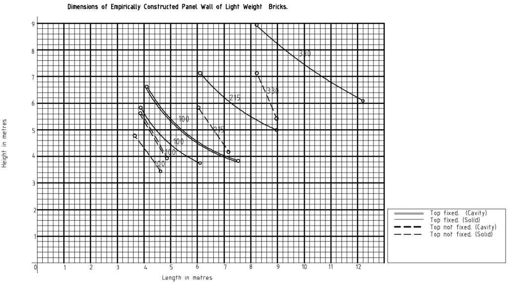
(2) They shall be reinforced in the highest four bed-joints with reinforcement consisting of two stands of steel wire of a diameter or not less than 3,55 millimetres, or two steel strips of equivalent cross-sectional area per bed-joint, and such reinforcement shall be lapped over a distance of at least 150 millimetres with the anchors to the supporting-columns required by section 27.
(3) Empirically constructed brick balustrade-walls shall be not less than 100 millimetres in thickness, and shall be laid in class A mortar and reinforced as required by subsection (2).
54. Dimensions Of Empirically Constructed Brick Partition-Walls.
The maximum height of empirically constructed brick partition-walls shall be set out in Table XII for the thickness, and unsupported length also set out in that Table.
TABLE XII
*Thinner partition-walls may be constructed, subject to the approval of the local authority.
55. Dimensions Of Empirically Constructed Brick Free-Standing Walls
(1) Free-standing brick walls of the minimum thickness shown in Table XIII shall not be constructed empirically to greater heights above the adjoining finished ground level than are set forth in that Table.
(2) Where the details of piers are given in Table XIII, every such wall shall be bonded into piers which, together with the thickness of such wall, shall comply with the minimum dimensions set forth in that Table and are spaced in accordance with the maximum dimensions laid in that Table.
(3) The foundation of every such wall shall project not less than 120 millimetres from the face of each side of such wall, and the piers, if any, in such wall shall not overhang such foundation.
(4) The upper surface of such foundation shall be not less than 150 millimetres below the adjoining finished ground-level at any point.
Table XIII
EMPIRICALLY CONSTRUCTED BRICK FREE-STANDING WALLS
*The largest dimension to be constructed at right-angles to the wall.
(5) Such foundation shall be of concrete which shall comply with the relevant requirements of section 14.
(6) No damp-Proof course shall be permitted between such wall and its foundation.
56. Dimensions Of Empirically Constructed Brick Retaining-Walls.
(1) Empirically constructed brick non-bearing retaining walls shall conform to the dimensions and be subject to the conditions prescribed in subsections (2) to (9).
(2) No superimposed loads, except pedestrian traffic shall be permitted behind the retaining wall within a distance equal to the height of the wall.
(3) No structure shall be erected on such wall except framed or wired fences no covered with sheeting and not exceeding 1,4 metres in height.
(4) The upper surface of the fill behind such a wall shall be approximately level.
(5) Expansion joints shall be provided in such retaining-walls at distances apart not exceeding 24 metres , and where piers are provided, expansion joints shall bisect piers.
(6) Every such retaining wall shall ne constructed vertical, shall be bonded into or cast integrally with piers which shall be built on the side of such wall remote from the fill and to the full height of such wall:
Provided that, where no details of piers are given in Table XIV, no piers are required.
(7) Every such pier shall have the minimum cross-sectional area set forth in Table XIV.
(8) Every such retaining-wall and its piers, if any, shall be built on a foundation of the minimum dimensions set forth in Table XIV, which foundation shall be constructed of concrete complying with the requirements of section 14.
TABLE XIV
DIMENSIONAL REQUIREMENTS OF EMPIRICALLY CONSTRUCTED NON-BEARING BRICK RETAINING WALLS AND THEIR PIERS AND FOUNDATIONS
(9) the upper surface of such foundation shall be at least 150 millimetres below the adjoining finished ground-level, and neither the retaining-wall nor any associated pier thereof shall overhang such foundation.
(10) Empirically constructed brick retaining-walls which are bearing walls shall comply, mutatis mutandis, with the requirements of section 46.
57. Requirements for Empirically Constructed Masonry of Blocks.
(1) Thickness.- Empirically constructed natural stone walls shall comply with the following requirements for thickness-
a) the thickness of ashlar stone walls shall be not less than that specified under the same conditions for solid brick walls in sections 44 to 56;
b) the thickness of squared rubble walls shall be not less than that specified under the same conditions for solid brick walls in sections 44 to 56, and in no case less than 230 millimetres for bearing-walls or less than 150 millimetres for non-bearing walls.
c) The thickness of random rubble walls shall be 150 millimetres greater than that specified under the same conditions for solid rock walls in sections 44 to 56, and in no case less than 330 millimetres for bearing-walls or less than 230 millimetres for non-bearing walls.
(2) Height and length of empirically constructed natural stone walls.- The height and length of any empirically constructed wall of natural stone shall be as prescribed by sections 44 to 56 for a solid brick wall of the same thickness:
Provided that, in the case of a random rubble wall, the height and length shall be as prescribed for a solid brick wall having a thickness 150 millimetres less than the thickness of the random rubble wall.
(3) Natural stone retaining walls.- Every empirically constructed natural stone retaining wall shall comply with the following requirements-
a) it shall comply with provisions of subsections (2) to (5) of section 56 for brick retaining walls:
Provided that a batter may be used on the outside face of the wall if it does not exceed 1 in 10;
b) its thickness at the top shall be not less that 230 millimetres, and, at any point below the top, its thickness shall be not less than 40 per centum of the height of wall above that point;
c) it shall be constructed on a concrete foundation at least 250 millimetres in thickness, projecting at least 150 millimetres beyond the edge of the base of the wall at either side, and constructed of concrete complying with the requirements of section 14;
d) its height shall not exceed 2 metres;
e) the mortar used in such wall shall be class A mortar.
58. Requirements For Empirically Constructed Masonry Of Natural Stone
(1) Thickness.- Empirically constructed natural stone walls shall comply with the following requirements for thickness-
a) the thickness of ashlar stone walls shall be not less than that specified under the same conditions for solid brick walls in sections 44 to 56;
b) the thickness of squared rubble walls shall be not less than that specified under the same conditions for solid brick walls in sections 44 to 56, and in no case less than 230 millimetres for bearing-walls or less than 150 millimetres for non-bearing walls.
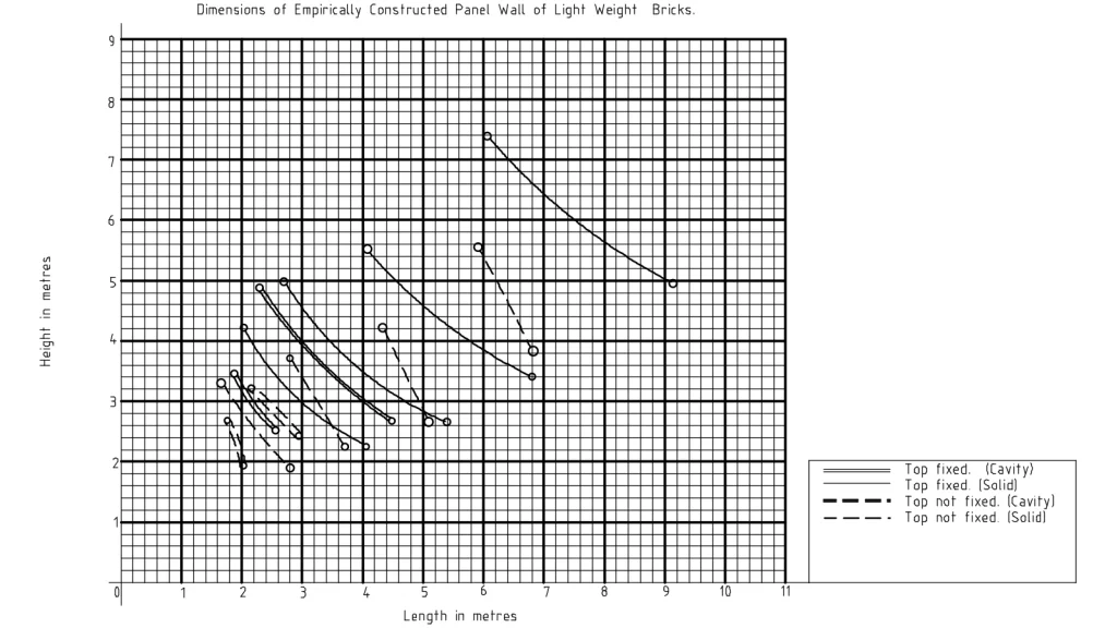
c) The thickness of random rubble walls shall be 150 millimetres greater than that specified under the same conditions for solid rock walls in sections 44 to 56, and in no case less than 330 millimetres for bearing-walls or less than 230 millimetres for non-bearing walls.
(2) Height and length of empirically constructed natural stone walls.- The height and length of any empirically constructed wall of natural stone shall be as prescribed by sections 44 to 56 for a solid brick wall of the same thickness:
Provided that, in the case of a random rubble wall, the height and length shall be as prescribed for a solid brick wall having a thickness 150 millimetres less than the thickness of the random rubble wall.
(3) Natural stone retaining walls.- Every empirically constructed natural stone retaining wall shall comply with the following requirements-
a) it shall comply with provisions of subsections (2) to (5) of section 56 for brick retaining walls:
Provided that a batter may be used on the outside face of the wall if it does not exceed 1 in 10;
b) its thickness at the top shall be not less that 230 millimetres, and, at any point below the top, its thickness shall be not less than 40 per centum of the height of wall above that point;
c) it shall be constructed on a concrete foundation at least 250 millimetres in thickness, projecting at least 150 millimetres beyond the edge of the base of the wall at either side, and constructed of concrete complying with the requirements of section 14;
d) its height shall not exceed 2 metres;
e) the mortar used in such wall shall be class A mortar.
59. Requirements For Empirically Constructed Masonry Of Soil-Cement Building Units.
Every empirically constructed wall of pre-cast soil-cement building -units shall comply with the following requirements-
a) a bearing-wall shall have a thickness of not less than 200 millimetres for a solid wall or not less than 150 millimetres for each leaf of a cavity-wall, and every partition-wall have a thickness of not less than 100 millimetres;
b) the storey-height of a bearing-wall shall not exceed 12 times its effective thickness, and its length shall not exceed 30 times its effective thickness;
c) wall-sections less than 600 millimetres in length between openings shall be regarded as providing no support to the wall above the openings, and such wall shall, according , be supported by a lintel spanning over both openings; and
d) every non-bearing wall shall comply with the requirements for a similar non bearing brick-wall, and shall have a minimum thickness of 100 millimetres and be subject to the provisions of section 35.
60. Requirements For Empirically Constructed Masonry Of Gypsum Blocks.
(1) Only non-bearing interior walls which are not likely to be exposed to continual dampness may be constructed of gypsum blocks.
(2) The dimensions of walls of gypsum blocks shall comply with the requirements for brick partition-walls set out in section 54.
61. Empirically Constructed Plain Normal Concrete Walls And Columns.
(1) Every empirically constructed bearing-wall, pier and column of plain normal concrete shall comply with the requirements of this section.
TABLE XV
(2) The effective thickness of such wall shall be not less than set out in Table XV for the same conditions as those set out in sections 44 to 56 for brick wall of the corresponding effective thickness.
TABLE XV
MINIMUM EFFECTIVE THICKNESS OF EMPIRICALLY CONSTRUCTED PLAIN NORMAL CONCRETE BEARING WALLS
| 1 | 2 |
| Corresponding effective thickness of solid brick wall millimeters | Minimum effective thickness of solid brick wall millimeters |
| 100 140 215 330 or greater | 100 125 200 330 or greater |
(3) The provisions of subsection (2) shall also apply to the effective thickness of stiffened walls determined in accordance with the provisions of subsections (5) to (10) of section 66.
(4) Reinforcement shall be placed around all openings, and reinforcing bars shall be distant not less than 25 millimetres above and not less than 50 millimetres below, and not less than 40 millimetres horizontally from every edge of every opening, and shall extend for a distance of not less than 48 times the bar diameter beyond the edges of the opening:
Provided that such distance may be reduced by the provision of hooks as specified in Chapter 3.
(5) Instead of providing reinforcement as required in subsection(4), a reinforcing bar may be replaced to extend diagonally past each corner of the opening, so as to pass not less than 50 millimetres from such corners and to extend not less than 600 millimetres in both directions from the point nearest to the corner of the opening.
(6) The mass of such reinforcement around openings shall be equivalent to that of one 10 millimetres bar for each 100 millimetres, or remaining portion thereof, thickness of the wall, and it shall be symmetrically disposed in the thickness of the wall.
(7) Plain, normal concrete piers cast integrally with such wall to its full height may be assumed to increase effective thickness as set out in subsections (6) and (9) of section 66 if such piers comply with the requirements of those subsections.
(8) Plain concrete columns shall be designed in accordance with the requirements of sections 63 to 82.
62. Empirical Construction In No-Fines Concrete.
(1) Every empirically constructed no-fines concrete bearing-wall shall comply with the requirements of the following subsections.
(2) Its thickness shall be as set out in Table XVI, except that, where it employs, light-mass aggregate and supports a flat, heavy roof, it shall be at least 50 millimetres greater in thickness than set out in Table XVI .
TABLE XVI
MINIMUM THICKNESS OF EMPIRICALLY CONSTRUCTED NO-FINES CONCRETE BEARING-WALLS
| 1 | 2 | 3 | 4 | 5 | |
| Storey | Minimum thickness of walls millimeters for | ||||
| Dwelling houses | Other buildings | ||||
| External | Internal | External | Internal | ||
| Topmost Storey or single Storey | 200 | 100 | 200 | 200 | |
| first below topmost Storey | 200 | 150 | 300 | 200 | |
| Second below topmost Storey | 300 | 200 | Not | Permitted |
(3) Such wall shall not be used in a storey other than those described in Table XVI.
(4) Where such wall is 200 millimetres or more in thickness, it shall have a storey height not exceeding 3,6 metres, and, where it is less than 200 millimetres in thickness, it shall have a storey height not exceeding 2,7 metres.
(5) Sections of wall between openings shall be not less in width than 450 millimetres, unless bridged over by a lintel as required by sections 17 and 18.
(6) Reinforcement shall be provided around openings as prescribed for walls of normal concrete, except that horizontal reinforcement shall be provided over each opening, as follows-
a) for a clear span exceeding 1,5 metres , a lintel of normal reinforced concrete, designed as such;
b) for a clear span of 1,5 metres or less, a lintel of reinforced no-fines or normal concrete:
Provided that a no-fines concrete lintel shall be not less than 300 millimeters in depth, and shall be reinforced with two 12 millimetre diameter steel bar or reinforcement of equivalent cross-sectional area.
63. Application of Certain Sections.
The provisions of sections 64 to 82 shall apply in the calculated design of masonry construction.
64. General Requirements For Design.
(1) Walls, piers and columns shall be so proportioned that the stresses in them due to the worst combination of forces to which they may be subjected 13 do not at any point exceed the values presented in sections 67 to 73 and section 78 for the several materials and conditions to which those sections relate.
(2) Provision shall be made for the transfer of all lateral forces to the ground without causing stresses in excess of those referred to in subsection (1).
65. Dispersion And Application Of Forces.
(1) In considering the transmission of forces through walls and other structural members of masonry and cast-in-situ concrete, the angle of dispersion of the forces through the material shall be taken as being not greater than 45 degrees from the direction of the forces.
(2) Roof-loads from trussed roofs or girder roofs shall be considered as being applied along a line passing through the centre of the bearing-area.
(3) Roof-loads from flat-slab roofs and floor-loads other than those from cantilevers shall be considered as being applied along a line which is related to the width of the bearing-areas as follows-
a) for slabs of normal concrete employing ordinary aggregate and bearing on the full thickness of the wall, and either extending on both sides of the supporting-wall or extending on one side only of such wall but having an effective span not exceeding 24 times the thickness of such slab, such line shall be assumed to be axial;
b) for timber floors and for slabs of concrete other than those described in paragraph (a) extending on both sides of the supporting-wall where the span on the one side of the wall does not exceed that on the one side by more than 50 per centum, such line shall be assumed to be axial.
c) For all roofs and floors, other than those described in paragraph (a) or (b), such line shall be assumed to be displaced from the centre of the bearing-area towards the span of the roof or floor(where there is only one span) or towards the larger span (where there are two unequal spans), and such eccentricity shall be deemed to be one-sixth of the width of the bearing of the roof or floor, whether or not this width of bearing is equal to the full thickness iof the supporting-wall.
66. Slenderness Ratio.
(1) Value of slenderness ratio.- The slenderness ratio of a wall shall be taken as the ration of the effective height to the effective thickness, or that of the effective length to the actual thickness, whichever ratio is smaller:
Provided that the slenderness ratio of a free-standing wall shall be taken as the ratio of the effective height to the effective thickness.
(2) The slenderness ration of a column shall be taken as the ratio of the effective height in the direction under consideration to the lateral dimension of the column in the same direction, or to the diameter, were the column is circular.
(3) Effective length.- The effective length of a wall shall be taken as two comma five times the unsupported length for a wing-wall, and as the unsupported length for any other type of wall14.
(4)Effective height.- The effective height of walls and columns for the conditions of lateral restraint indicated in the Table shall be set out in Table XVII , where H is taken as-
a) for a bearing-wall or curtain-wall, the height of the storey;
b) for a panel-wall or a partition-wall or a partition-wall or a column, the actual height from the top of the floor construction, collar-beam or frame-work above;
c) for a free-standing wall or a wing-wall, the actual height.
(5) Effective thickness.- The effective thickness of a solid wall, without piers, shall be the actual thickness of such wall.
(6) The effective thickness of a solid wall stiffened by piers bonded shall be obtained by multiplying the actual thickness of such wall by the factor given for the dimensions and spacing of the piers in Table XVII if the width of the pier parallel to the length of the wall is not less than twice the actual thickness of the wall, tw, and the total thickness of the pier (including the thickness of the wall), tp , is not less than 2tw:
Provided that bonded intersecting-walls of a thickness not less than tw may be regarded as piers of effective pier-thickness tp14 equal to half the unbroken length of the intersecting-wall plus the thickness of the stiffened wall.
TABLE XVII
EFFECTIVE HEIGHT OF WALLS AND COLUMNS
| 1 | 2 | 3 |
| Member | Condition of restraint at top | Effective Height |
| walls | fully restrained……………………………………… Moderately Restrained……………………….. unrestrained ……………………………………… | 0.75H 1.0H 1.5H |
| columns | fully restrained…………………………………….. unrestrained ……………………………………….. | 1.0H 2.0H |
TABLE XVIII
FACTORS FOR EFFECTIVE THICKNESS OF STIFFENED MASONRY AND CONCRETE WALLS
(Effective thickness= actual thickness x factor)
13 The minimum forces for which provision must in all cases be made are set out in Chapter 3.
14 See definition of “length of wall”.
(7)When the thickness of a wall is changed between the bottom and the top of a storey or of a wall, its effective thickness shall be calculated by multiplying the thickness of each section of constant thickness by its heights and dividing the sum of their products by the total height of the wall.
(8) The effective thickness of an unstiffened cavity-wall shall be found from the expression
te = 2/3 (to – w), where-
te = effective thickness; and
to = overall thickness; and
w = width of cavity.
(9) The effective of a cavity-wall stiffened by piers shall be taken as the effective thickness of the unstiffened wall multiplied by the factors specified in Table XVIII for the size and spacing of piers concerned:
Provided that-
i) the over-all thickness of the wall, to, shall be used in place of tw in determining the minimum size and spacing of piers; and
ii) piers are bonded to one leaf of the wall.
(10) Where, in a cavity-wall, one leaf is designed to carry total superimposed load, the permissible stress for that leaf shall-
a) be based on the slenderness ration calculated from the effective thickness of the whole wall; or
b) be take as the actual thickness of the load-bearing leaf;
whichever gives the smaller value of the slenderness ratio.
(11) Permissible limits of the slenderness ratio.- The slenderness ratio of walls and columns shall not exceed the value given for the relevant conditions in Table XIX .
TABLE XIX
PERMISSIBLE LIMITS OF SLENDERNESS RATIO
67.Basic Stresses For Brick Masonry.
(1) For solid masonry building-units of the dimensions of bricks, the stresses in masonry due to axial vertical loads calculated as evenly distributed stresses over-
a) the cross-sectional area of a wall; or
b) if there are openings in a wall, the reduced cross-sectional area between openings; or
c) the cross-sectional area of a column;
shall not exceed the stresses set out in Table XX for the compressibe strength of such units and class of mortar set out in that Table:
Provided that-
i) the slenderness ratio does not exceed 12; and
ii) the compressive strength of such masonry building-units is determined in the manner described in section 5 for the building-units concerned.
TABLE XX
BASIC STRESSES FOR MASONRY WALLS AND COLUMNS
(2) The permissible stresses set out in Table XX shall be designated the basic stresses for masonry.
(3) Basic stresses for intermediate strengths of the building-units aforesaid may be obtained by liner interpolation between the stresses set out in any one column of that Table.
68. Stresses For Large Slenderness Ratios.
(1) When all other conditions are as stated in section 67, with the exception that the slenderness ratio exceed 12, but does not exceed the values set out in Table XIX, then the stresses in masonry shall not exceed the basic stresses set out in section 67 multiplied by the factors set out in Table XXI.
TABLE XXI
(2) The factors corresponding to intermediate slenderness ratios shall be found by linear interpolation.
69. Axial Stresses In Block Masonry .
(1) The axial stresses in masonry constructed of blocks may be increased to not more than one and a half times the values set out for brick masonry in sections 67 and 68 for the conditions described therein.
(2)The stresses in masonry constructed of cellular or hollow blocks shall not exceed those for solid blocks , and the compressive strength of cellular or hollow blocks, and the stresses on them, shall be computed on their gross cross-sectional area.
(3)The stresses in masonry built of units which have dimensions different from those prescribed for bricks or blocks shall not exceed the following values, based on the height of the units as laid in the wall-
70. Axial Stresses In Cast-In-Situ Concrete.
(1)Where the slenderness ratio does not exceed 15, the stresses due to axial vertical loads in-
a) cat-in-situ plain concrete walls computed as evenly distributed over-
i) the cross-sectional area of the wall; or
ii) if there are openings in the wall, over the reduced cross sectional area between openings; and
b) plain concrete columns;
shall not exceed those set out in Table XXII for the appropriate type of concrete.
TABLE XXII STRESSES PERMITTED IN CONCRETE WALLS AND COLUMNS
(2) Where the slenderness ration of any wall referred to in subsection (1) exceeds 15, but does not exceed the values set out in Table XIX, the stress in such wall shall not exceed the figure obtained by multiplying the stress specified in subsection (1) by the appropriate factor set out in Table XXIII
TABLE XXIII
STRESS FACTORS FOR SLENDER CONCRETE WALLS.
71. Axial Stresses In Natural Stone Masonry
The stresses in masonry constructed of natural stone due to axial loads shall not exceed those set out in Table XXIV for the kind of stone, type of walling an class of mortar set out in that Table:
Provided that, if class A mortar is used, such stresses may be increased to 10 per centum of the crushing strength of the stone proposed to be used, as measured on representative samples, to the satisfaction of the local authority.
TABLE XXIV
AXIAL STRESSES PERMITTED IN NATURAL STONE WALLS.
72. Stresses Due To Eccentric Or Lateral Forces.
(1) When the eccentric or lateral forces, together with axial loads, have to be taken into account in walls, piers or columns, the stresses shall be calculated on the assumption that the straight-line theory applies to such walls, piers or columns as are subject to bending moments, that is to say that planes in the cross-section remain places after bending.
(2) On this assumption, the maximum stresses in any part of the walls, piers or columns aforesaid resulting from eccentric loads and lateral forces, together with the axial loads, shall not exceed those set out in Table XXV:
Provided that any excess in compressive stress over that permitted for axial vertical force is due entirely to the eccentricity of forces or to lateral forces.
TABLE XXV
PERMISSIBLE STRESSES, OTHER THAN AXIAL COMPRESSIVE, IN MASONRY
73. Stresses Under Concentrated Loads.
When the combined effects of axial, eccentric and lateral forces are all taken into account, the local under the ends of lintels or under column-bases or other concentrated loads shall not exceed the average stresses permitted by sections 67 to 72 for axial vertical loads alone by more than 50 per centum.
74. Reinforced-Concrete Walls And Columns.
(1) Reinforcement, mixing and placing of reinforced-concrete walls. – Reinforcing of concrete walls shall be carried out, and the concrete shall be mixed and placed, in accordance with the requirements of Chapter 3.
(2) Design and thickness of reinforced-concrete walls. -Reinforced-concrete walls shall be designed and constructed in accordance with the provisions of Chapter 3, and shall in all cases be of the following minimum thickness-
a) basement-walls and foundation-walls, 150 millimetres;
b) exterior and interior bearing-walls, 100 millimetres.
(3) The thickness of the leaves of cavity-walls shall not be less than that of brick walls under the same conditions:
Provided that-
i) where 100-millimetre thickness is required for brickwork, 75 millimetres may be used for reinforced concrete;
ii) in dwelling-houses of a height not exceeding two storeys or 7,5 metres, whichever is the lesser, leaves or cavity-walls may be less than 75 millimetres in thickness, bust shall be not less than 40 millimetres in thickness for an unsupported length not exceeding 24 times the effective thickness;
iii) in single-storey dwelling-houses, leaves of cavity-walls shall be not less than 50 millimetres in thickness for an unsupported length exceeding 24 times but not exceeding 40 times the effective thickness.
(4) Reinforced-concrete columns.- Reinforced-concrete columns shall de designed in accordance with the provisions of Chapter 3.
75. General Requirements For Reinforced Brickwork.
(1) The design of buildings and structural members in buildings constructed of reinforced brickwork shall be based on the same general principles of design and analysis as are adopted for the design of similar members and structures of reinforced concrete.
(2) The stresses in such members and structures shall not exceed the limits set out in sections 76 to 82.
76. Materials For Reinforced Brickwork.
In reinforced brickwork-
a) bricks shall have a compressive strength of not less than 14 megapascals;
b) reinforcement shall comply with the requirements for reinforcement set out in Chapter 3;
c) mortar materials shall be required by section section 5.
77. Mortar And Grout For Reinforced Brickwork.
(1)Mortar used in reinforced brickwork shall be of class A or class B.
(2)Mortar used for grouting shall be of class A or class B, with additional water in order to produce a consistency which will enable such mortar, or grout, to be poured without causing segregation.
(3)Grout shall not be used in horizontal joints.
Permissible Stresses In Reinforcement Brickwork
78. Permissible Stresses In Reinforcement Brickwork
(1) The stresses in reinforced brickwork shall not exceed, in any part, the values set out in Table XXVI .
(2) The direct compressive stress and the compressive stress due to bending in members with slenderness ratios other than 12 shall not exceed the values set out Table XXVII for the strength of brick concerned, multiplied by the factor (F) set out in Table XXVIII for the slenderness ratio of the member considered.
TABLE XXVI
PERMISSIBLE STRESSES IN REINFORCED BRICKWORK
79.Detailed Requirements For Reinforced-Brick Columns.
a) the total cross-sectional area of the longitudinal steel reinforcement shall not be less than 0,4 per centum of the gross cross-sectional area of the column;
b) there shall be at least one bar for each salient angle in the cross-section of the column;
c) lateral ties shall be provided of a total volume of not less than 0,4 per centum of the gross volume of the column, and shall have a diameter of not less than 6 millimetres;
d) the lateral ties shall have their ends anchored , welded together or lapped through a distance equal to 50 times the diameter of the longitudinal bars or the least lateral dimension of the column, whichever is the least.
e) The spacing of the lateral ties shall not exceed 400 millimetres or 16 times the diametre of the longitudinal bars or the least lateral dimension of the column, whichever is the least.
80. Detailed Requirements For Reinforced-Brick Walls.
In reinforced-brick walls, the following requirements shall be complied with-
a) where-
i) the stresses in bearing-walls designed in accordance with sections 75 to 82 exceed those permitted in sections 67 and 68; and
ii) such walls are required to sustain lateral forces or loads with an eccentricity greater than one-sixth of the thickness of the wall;
the bricks which compose the walls shall be slotted or grooved so as to permit the accommodation of the vertical reinforcement and its required covering of grout without relying on the vertical joints between the bricks;
b) where openings in the wall have a height greater than 12 times the width of the brickwork between openings, the walling between the openings shall be designed as a column.
81. Cover Over Reinforcement In Reinforcement Brickwork.
(1) In reinforcement brickwork, the reinforcement shall have the cover prescribed by this section:
Provided that the local authority may require a cover greater than that so prescribed where it considers that the latter is not adequate to prevent corrosion of the reinforcement under the particularly corrosive conditions which exist at the building site.
(2) The cover of mortar or grout in the joints between reinforcement and bricks shall be not less than one-quarter of the diameter of bars or thickness of strip, and in no case less than 3 millimetres.
(3) The minimum clear distance, disregarding applied surface finishes, of bar reinforcement from exterior (exposed) faces of brickwork shall be 40 millimetres.
(4) The minimum clear distance, disregarding applied surface finishes, of bar reinforcement from interior faces of brickwork shall be as follows-
a) for slabs, walls and beams, 20 millimetres or the bar diameter, whichever is the greater;
b) for columns, 25 millimetres;
c) for any structural member in contact with the soil, such as a footing, foundation or retaining wall, 75 millimeters.
Chapter 6 : Miscellaneous Materials and constructions.
1. Interpretation Of Terms.
“back filling” means the material with which a trench or excavation is refilled;
“butt exposure” means the length of a slate, shingle or tile which is exposed below the edge of the next row of units above when laid on the roof;
“corrosion-resistant” means having the ability to resist gradual chemical or electro-chemical change caused by atmosphere, moisture or other agents;
“damp-roof” means having the ability to prevent passage of moisture in the absence of hydrostatic pressure;
“finished ground-level” means the permanent surface of the ground adjoining the building as distict from the ground-level before commencement of building-operations;
“glazing -bars” means bars made with rebates or of special shapes to support panes of glass in position, and to which the panes may be secured;
“habitable room” means any room designed for human occupation, but excluding bath-rooms, water-closets, stairways, passageways, lift-cars, photographic dark rooms, sculleries, domestic laundries, cold rooms or garages used for parking only;
“roof-pitch” or “roof-slope” means the inclination of a rather or roof to the horizontal measured in degrees of arc;
“safety-glass” means laminated safety-glass, solid heat-treated safety-glass (toughened glass), wired glass or polished wired glass;
“side-lap” or “end-lap” means the distance by which one roofing-unit overlaps the next at its side or end;
“waterproof” means having the ability to prevent the passage of water under hydrostatic head;
“water-table” means the level of the free surface of undisturbed water which will stand in any excavation on the upper limit of the zone of saturation by water in the ground;
“weatherproof” means having the ability to prevent the entry of water into a building under unobstructed conditions of runoff.
2. General Requirements For Damp-Proofing And Waterproofing .
The following requirements apply regarding damp-proofing and waterproofing-
a) subject to the provisions of paragraph (c), there shall be provided, in the erection of every building, damp-proofing or water-proofing, in accordance with the requirements of this Chapter;
b) water or moisture shall be prevented from entering the interior of such building, except as provided for in subsection (6) of section 9;
c) the local authority may permit the oimission of damp-proofing or water proofing in any building in which there are no habitable rooms, and where the person intending to erect such building can show to the satisfaction of the local authority that no danger to the health of persons or to the stability of the building will be caused by the entry of moisture or water into the building;
d) damp-proofing and waterproofing materials shall comply with C.A.S. No A25. Damp-proofing materials, or be other material approved by the local authority;
e) mastic asphalt damp-proof courses shall be applied in at least two layers;
f) damp-proofing and water proofing procedures following S.A.B.S. O21, Waterproofing of buildings, shall be deemed to satisfy the requirements of this section.
3. Detailed Requirements
(1) Horizontal damp-proof courses.-Every horizontal damp-proof course shall be constructed to the full width of the wall resting upon it, and shall also extend full width of any wall-plate which may rest upon the damp-proof course.
(2) For the purpose of this section, a cavity-wall shall be regarded as two separate walls.
(3) Where composed of sheeting, horizontal damp-proof courses shall be lapped not less than 100 millimetres at the joints.
(4)Vertical damp-proof courses.-If in any solid wall the horizontal damp-proof course is not situated at least 150 millimetres above the finished ground-level, a vertical damp-proof course (or water course if required) shall be taken up the outer face of the wall from the horizontal damp-proof course to at least 150 millimetres above the external-finished ground-level, and there finished off in such a manner as to prevent the entry of moisture; and shall be protected by brick-work of not less than 65 millimetres in thickness, or by such other method as may be approved by the local authority.
4. Cavity-Walls.
In cavity-walls, damp-proof courses shall be provided in such a manner as to-
prevent moisture from the soil or foundation-walls from rising into the wall above the level of the ground-floor or reaching any timber in the floors; and
a) allow any moisture from the cavity to drain outwards through weep-holes or open vertical joints left at intervals in the outer leaf of such walls.
5. Cavity-Walls
In cavity-walls, damp-proof courses shall be provided in such a manner as to-
prevent moisture from the soil or foundation-walls from rising into the wall above the level of the ground-floor or reaching any timber in the floors; and
a) allow any moisture from the cavity to drain outwards through weep-holes or open vertical joints left at intervals in the outer leaf of such walls.
6. Openings In External Cavity-Walls.
In external cavity-walls, damp-proof courses shall be provided at sills and heads of all openings, to prevent the passage of moisture from the outer to the inner leaves of the wall.
7. Parapets And External Projections.
Damp-proof courses shall be provided to parapets and, where required by the local authority, to external projections in such manner as to prevent the passage of moisture into the building.
8. Floors.
(1) General.-Solid floors in contact with the ground shall be a minimum thickness of 75 millimetres and shall be so constructed or treated as to render them damp-proof.
(2) Where required by the local authority, a horizontal damp-proof course shall be laid under the floor for its full extent.
(3) Wash-room and toilet-room floors.- The floors of wash—rooms and toilet-rooms shall be of tile, terazzo, granolithic and other impervious material, and have a skirting of impervious material of not less than 75 millimetres in height around the walls.
9. Basements.
(1) Floors.-Basement-floors shall be-
a) damp-proof; and
b) where ground-water is present or is likely to rise above such floor -level and is to be drained away from the building, the floor shall be laid on a layer, of not less than 100 millimetres in thickness, of broken stone, rubble or other fragmented material, the underside of which layer shall be above the top of the footing of any wall or column.
(2) Walls.- Basements-walls shall be provided with vertical damp-proof courses where damp-proof courses are required by section 2, and shall be in accordance with the provisions of section (4) of section 3.
(3) Where ground-water is present or is likely to rise above basement-floor level and is to be drained away from the building, a layer of fragmented material of not less than 75 millimetres in horizontal thickness shall be placed between the walls and any back-filing. Such layer shall-
a) communicate with the layer of similar material under the floor; and
b) extend to a level of 150 millimetres above the highest level of the water-table.
(4) Junction of floor and wall.-The junction between basement-floors and walls and columns shall be rendered damp-proof, unless, in the case of internal walls and columns, the floor itself has been rendered damp-proof or waterproof.
(5) Disposal of ground-water.-Where ground-water is present or is likely to rise above the basement-floor level and such water is to be prevented from entering the building-
a) means shall be provided by gravity or by pumping effectively to drain the water from the fragmented material around the walls and from under the floor of the basement; or
b) the basement shall be made waterproof to a level of at least 150 millimetres above the highest level of the water-table at the site.
(6) Where water is to be allowed to enter any building, weep-holes shall be made in the lowest floor or in the walls as such floor-level, and the water led by channels to a sump from where it shall be pumped away to a discharge-point indicated by the local authority.
10. General.
(1) Roof-coverings.- All roofs and roof projections of buildings shall be weatherproofed and shall be covered with one or more of the coverings detailed in this Part.
(2) The coverings shall be secured so as withstand climatic conditions, such as wind pressure, wind suction and changes in temperature.
(3) Notwithstanding the restrictions placed on the profiles and sizes of roof coverings in sections 13 to 21 and the B.S., S.A.B.S. and C.A.S. mentioned therein, alternative profiles and sizes of the respective materials may be used, if approved by the local authority.
(4) Substructure.- The trusses, rafters, purlins or other supporting framework to roof-coverings shall be designed in accordance with the respective requirements for concrete, steel or timber, contained in these by-laws.
(5) Timber battens and purlins shall be provided of such strength, dimensions and spacing as shall adequately support the roof covering applied to them, together with all superimposed and wind loads, to the satisfaction of the local authority.
(6) Roofs with more than one kind of covering.-Where a roof-covering is provided over another roof-covering, the minimum roof-pitch shall be taken as the minimum pitch allowable.
(7) Flashing.-Flashing shall be provided so valley and the junction of roofs with chimneys, parapets and other abutting surfaces, so as to render the roof weatherproof, and such flashings shall comply with the following requirements-
a) they shall be corrosion-resistant;
b) they shall be composed of soft copper, zinc, aluminium, hard lead, galvanized metal, asbestos-cement or other approved material having similar corrosion-resistant qualities. Zinc flashings shall have a mass of not less than 4 kilograms per square metre, and lead flashings of not less than 15 kilograms per square meter. The minimum thickness for flashings of copper, galvanized metal or aluminium shall be 0,55 millimetre. Asbestos cement flashings shall be at least 5 millimetres in thickness;
c) whenever a metal flashing or other metal fitting is used in conjunction with a dissimilar metal, whether of the roof or another fitting, which may lead to electrolytic corrosion between them, provision shall be made to prevent such corrosion by painting on contacting surfaces wit bitumen-based paint or by any other method which will prevent a galvanic couple being formed;
d) flashings to the junction of roofs with chimneys, parapets and other abutting surfaces shall be in two pieces. The underneath flashing shall extend at least 100 millimetres up vertical surfaces and shall be covered with the second flashing which shall be securely wedged and pointed.
11. Mastic Asphalt Roofing
The mastic asphalt used for roofing shall comply with the requirements of C.A.S. No. A1, Mastic asphalt for roofing (limestone aggregate), or shall otherwise be to the satisfaction of the local authority.
12. Bituminous-Felt Built Up Roof-Coverings.
Bituminous-felt built-up roof coverings shall comply with the following requirements-
a) the exposed layer or layers shall comply with the requirements of C.A.S. NO. A30, Bitumen roofing felt surfaced with natural mineral granules of slate or stone rolled into the surface during manufacture in such a manner as to form a closely compacted surface;
b) unexposed layers shall be of mineral-stabilized asphaltic roofing felt or asphalt-saturated felt;
c) such coverings shall be laid on a continuous deck of tounge-and-groove wrought timber boarding or concrete or other approved material, with a minimum fall of 1 in 70 torwards rainwater outlets;
d) when the slope of a roof exceed 1 in 4, the built up roof covering shall be fixed to the deck.
13. Asbestos-Cement Roof-Slates.
(1) Asbestos-cement slates shall comply with the requirements of B.S. 690 or C.A.S. 198.
(2) Slates shall be laid so that the following requirements are met-
a) each course shall overlap the second course below it by not less than-
(i) for a diamond or honeycomb pattern, 75 millimetres ; and
(ii) for rectangular pattern, 100 millimetres;
b) for diamond or honeycomb-pattern slates, the roof-slope shall be not less than 25 degrees;
c) for rectangular-pattern slates, the roof slopes shall be not less than 17 ½ degrees;
d) where additional weatherproofing is provided to the satisfaction of the local authority, the roof-slopes referred to in paragraphs (b) and (c) may be reduced.
14. Asbestos-Cement Roof-Sheeting.
(1) Asbestos-cement corrugated sheets for roofing shall comply with requirements of C.A.S. 198 or B.S. 690, and asbestos-cements ridging , barge-boards , flashings and other accessories shall be of material of similar quality and thickness
(2) Except as provided for in subsection (3), where asbestos-cement roof-sheeting is used on a roof, the roof shape shall be not less than 10 degrees, and the minimum side-laps and end-laps shall be in accordance with Table 1.
TABLE 1
MINIMUM SIDE-LAPS AND END-LAPS FOR ASBESTOS-CEMENT ROOF-SHEETING
(3) Where asbestos-cement roof-sheeting is used on a roof and the roof-slope is less than 10 degrees, both side-laps and end-laps must be sealed with a non-hardening compound.
15. Asbestos-Cement Decking Units.
(1) Asbestos-cement decking-units shall comply with the requirements of B.S. 3717.
(2) Asbestos cement decking units shall be laid and fixed to the satisfaction of the local authority.
16. Galvanized -steel roofing
17. Aluminum and Aluminum-Alloy Roofing.
(1) General.- Aluminium and aluminium-alloy roofing shall be protected from any dissimilar metal, and from concrete or mortar on which it may rest, by a layer of suitable bitumen-based or coal-tar pitch-based paint between the contact surfaces or by an insulating material approved by the local authority.
(2) Corrugated-aluminium roofing.- Corrugated-aluminium-alloy roofing shall comply with the following requirements-
a) where the corrugation pitch is between 65 millimetres and 80 millimetres and the depth of corrugation is 19 millimetres ± 1 millimetre, the thickness of sheet shall be not less 0,7 millimetre, and the maximum purlin spacing, measured centre to centre, shall be 1,2 metres for the 0,7 millimetre sheet;
b) the requirements for laps and minimum slope shall be as set out in paragraphs (a) and (b) of subsection (2) of section 16 for corrugated-steel sheets.
(3) Aluminium flat-sheet roofing laid in a deck.- Where aluminium or aluminium-alloy roofing in the form of a flat sheets is laid on a deck, the following requirements shall be met-
a) where the roofing is a single-layer weather-proof covering, the minimum thickness of sheet shall be 0,5 millimetre;
b) the deck shall be continuous and shall comply with the requirements of paragraph (c) of section 12, except that timber may be unwrought and butt-joints.
(4) Aluminium-foil built-up roof coverings.- Where aluminium foil is used for built-up roof-coverings on a continuous concrete or boarded deck, the following requirements shall be met-
a) where such a foil is used as a single-layer covering for a bituminous-felt built-up roof-covering, or where such foil is used in a built-up roof-covering of successive layers, the thickness of foil shall be not less than 0,05 millimetre and not more than 0,1 millimetre;
b) where such foil is used as a single-layer covering over concrete roofs or over bituminous felt on a boarded deck the thickness of foil shall be not less than 0,08 millimetre and not more than 0,1 millimetre;
c) the foil shall be embossed to ensure good adhesion and to allow for expansion;
d) the deck shall comply with the requirements of paragraph (c) of section 12, or be a shell-type concrete roof, steel-rowelled to a smooth finish after having attained its initial set;
e) when laid on a flat deck without bituminous felt, a minimum of two thickness of foil shall be laid in shingle pattern, with use of an approved grade of hot bitumen or cold adhesive;
f) when foil is laid on shell-type roofs, an approved cold adhesive shall be used. If only a single thickness of foil is required, there shall be a lap of at least 100 millimetres at any joint.
(5) Aluminium fluted-sheet roofing (long-span custom).- Aluminium fluted-sheet roofing shall comply with the following requirements-
a) the roof-slope shall be not less than 3 degrees with the sheets seam-bolted together at all side-laps with aluminium seam-bolts of not less than 6 millimetres diameter, and the minimum side-laps and end-laps of sheets and the maximum seam-bolting centres shall be in accordance with Table IV;
TABLE IV
b) where the roof-slope is less than 10 degrees, the end-lap shall be sealed with an approved mastic sealer
18. Copper-Sheet Roofing
(1) General.- Copper sheets for roofing, including clips, shall be not less than 0,55 millimetres in thickness, and shall be made from hot rolled-sheet of dead-soft temper.
(2) Detailed requirements.- Copper sheets for roofing shall be laid on a deck complying with the requirements of paragraph (c) of section 12, except that timber decks may be unwrought and butt joined.
19. Slanted Roofing.
(1) Roof-slates shall be of impermeable fine-grained rock, free from knots and knurls, and of such nature and so located that the durability or weatherproofing of the roof is not adversely affected thereby.
(2) Roof-slates shall, in addition, meet the following general requirements-
a) every slate shall be of uniform thickness throughout, which shall be not less than-
(i) 5 millimetres for all sizes not larger than 300 x 250 millimetres;
(ii) 6 millimetres for all sizes larger than 300 x 250 milimetres;
b) slates shall have a water absorption not exceeding 0,8 per centum of their dry mass, when subjected to the test set out in the First Schedule;
c) the width of each slate shall be at least half its length;
d) for slates laid on open battens, the roof slope shall be not less than 30 degrees, except as provided for in paragraph (e), and the sizes of slate used shall comply with those given in Table V for the appropriate roof-slope;
TABLE V
e) where additional weatherproofing to the satisfaction of the local authority, the roof-slope may be less than 30 degrees, and in that case shall be not less than 20 degrees.
20. Concrete Roofing Tiles
21. Clay Roofing Tiles
(1) Marseilles-pattern and plain-clay roofing tiles shall comply with the requirements of S.A.B.S. 623, Clay roofing tiles.
(2) Clay roofing tiles, other than Marseilles-pattern and plain tiles, shall be made accurate to their nominal dimensions with the following tolerances-
a. thickness: 2 millimetres(for plain tiles tiles only);
b. breadth: ±3 per centum of nominal breadth;
c. length: ± 3 per centum of nominal length.
(3) Detailed requirements.- The detailed requirements for clay roofing tiles shall be in accordance with the provisions of subsection (2) of section 20.
22. Cut Wooden Shingles2.
(1) Impregnation and moisture content.- Cut wooden shingles shall be impregnated in accordance with the requirements in accordance with the requirements of S.A.B.S. 448, South African wood shingles for roofs and walls, and shall also conform to the moisture-content clause of that specification.
(2) General requirements.- Cut wooden shingles shall comply with the following requirements-
a. shingles shall taper from butt to tip and shall be made to the following requirements-
(i) the nominal lengths of shingles shall be not less than 400 millimetres;
(ii) the widths of shingles shall be any random width from 100 millimetres to 200 millimetres;
b) the maximum permissible butt exposure shall vary with the roof slope, in accordance with Table VI;
c) values of maximum permissible butt exposure for roof-slopes between 26 and 34 degrees, and for shingles of different length from that specified in paragraph (a), shall be obtained by linear interpolation;
d) in no case shall the roof-slope be less than 20 degrees.
TABLE VI
23. Thatching 2.
The following requirements apply in regard to thatching-
a) the thickness of the thatching shall be not less than 130 millimetres at any part of the roof, and shall consist of not less than two layers of bundles of thatching;
b) at eaves the verges, there shall be layer of bundles of thatching additional to those required in paragraph (a);
c) at valleys, hips and ridges, approved soakers shall be provided which shall be covered with a layer of bundles of thatching additional to those required by paragraph (a), and the total thickness shall be not less than 200 millimetres;
d) except as provided for in paragraph(e), the slope of the roof shall be not less than 45 degrees;
e) when a thickness of thatching double that required under paragraph (a) is provided, the slope of the roof may be reduced to 35 degrees.
24. Glass In Roofing 3.
1 General.- Where glass is employed as a roofing-material or in vertical glazing or louvres at a height of more than 3,5 metres above the level of the interior floor concerned, the glass shall be of one of the types listed in Table VII, and shall comply with the requirements for that type.
TABLE VII
(2) Notwithstanding the provisions of subsection (1), sheet glass may be used in vertical glazing where the area of any one pane does not exceed 0,25 square metre and is supported on all sides and, where louvres form a part of the vertical glazing, the nominal thickness of sheet glass in the louvres shall be not less than 5,5 millimetres.
(3) Width of flat glass in roofing.-The maximum permissible width of all types of flat glass referred to in Table VII, shall be 600 millimetres, and such glass shall be supported at least along both long edges.
(4) Roof-slopes.- The minimum roof-slope for glass roofing on a uniform pitch shall be 20 degrees, except in the case of glass tiles, which shall have the same slope as laid in section 21 for clay roofing-tiles of the same type.
(5) Glazing-bars.- Glazing-bars shall conform to the requirements of one of the following paragraphs –
a) they shall be constructed in accordance with one of the following subparagraphs, being made of-
(i) a steel section sealed with integrally extruded lead sheath-covering (the mass of lead shall be not less than 10 kilograms per square metre, giving a minimum thickness of 1 millimetre);
(ii) a galvanized-steel bar, the zinc coating of which shall be not less than 600 grams per square metre with a capping of non ferrous metal;
(iii) a composite bar consisting of a timber supporting bar with a non ferrous metal section on top to receive the glass, and with a capping of similar metal;
(iv) a reinforced-concrete bar, with approved capping;
(v) a bar of aluminium alloy, with a capping or weathering-wings of aluminium or lead;
or
b) they shall be made of, or sheathed with, corrosion-resistant material, to the satisfaction of the local authority.
2 See the requirements of Chapter 11 for restrictions on the use of this type of roofing
3See section 27 for the method of glazing to be used.
25. General Requirements.
Glass for glazing shall be of the type mentioned, and of the minimum nominal thickness and mass per square metre shown against each individual type in section 26.
26. Minim Nominal Thickness Of Glass For Glazing.
(1) Subject to the provisions of subsection (1) of section 24 and to provisions of subsections (3), (4) and (6), the minimum nominal thickness and masses per square metre of glass for vertical glazing in buildings, other than roofs, shall be as set out in Table VIII for each type of glass shown.
(2) The maximum glazing-sizes for the corresponding masses per square metre and nominal thickness of sheet glass and polished plate glass shall be determined by reference to the Second Schedule and Figures 1 and 2 in the Schedule, and these sizes shall not be exceeded except where the opening to be glazed is nowhere more than 3,5 metres above the level interior floor concerned, when the width may be increased by 20 per centum.
(3) Where glass is used in doors, in panes framed on all edges and larger than 0,5 square metre in area, it shall be safety-glass of a thickness to the approval of the local authority for the size of pane concerned.
(4) where glass doors are unframed, they shall be of safety-glass of thickness to the approval of the local authority.
(5) Where transparent glass is used in doors, either framed or unframed or in vertical glazing situated between floor-level and a height of 2 metres above floor level, and, in opinion of the local authority, the presence of the glass may not be apparent to, or suspected by, a person approaching it, the glass shall bear markings which render the glass clearly apparent, except that, where a close approach to the glass is prevented by barrier-wails or other approved means of preventing an accidental collision with the glass, such markings shall not be required.
(6) Any glass louvre, wherever situated, unless supported on both edges shall have a minimum thickness of millimetres and shall have both edges ground smooth.
27. Method Of Glazing.
Glazing shall be carried out with such materials as will ensure the glass is securely held in surrounding frames or openings and is capable of resting wind pressure and rain penetration, and will not be dislodged by normal movement of frames designed to move to which the glass is fitted.
28. Cast Iron In Buildings.
(1) Material specification.- Cast iron used for structural members in buildings shall be of grade not less than Grade 10 of B.S. 1452.
(2) Permissible stresses.- The permissible stresses in cast-iron structural members shall not exceed the values given below in megapascals-
Tension in bending 21
Axial tension 21
Shear 14
Axial compression (bearing) 83
Compression in bending 42
Compression in columns 83-28 l/r where l/r, the slenderness ration, is the ration of the actual length of the member to the least radius of gyration of its cross section.
(3) If a cast-iron column is not symmetrical about both longitudinal axes, and is not supported laterally between its ends, its slenderness ration shall be determined by the methods detailed in appropriate standard in Chapter 3.
(4) Columns and compression-members.- No cast-iron column or other cast-iron compression-member shall have a length, l, exceeding 100 times its least radius of gyration, r.
(5) The ends of all cast-iron columns shall be fixed in position and direction.
29. Methods Of Protection Against Corrosion.
All iron and steel structures used in building shall be coated to comply with the following codes of practice-
IRON B.S. CP 2008 Protection of iron and steel structures from corrosion
STEEL B.S. CP 2008 Protection of iron and steel structures from corrosion, and
B.S. 3189 Phosphate treatment of iron and steel.
Chapter7: Water Supply.
1. Interpretation Of Terms
In this Chapter –
“Communication-pipe” means any pipe leading from a main to the premises of any consumer as far as the street boundary of such premises situated nearest to such main or, in cases where a meter is installed inside the premises of any consumer, as far as the inlet of the meter;
“consumer” means the occupier of any premises which the local authority has agreed to supply with water, or the owner of such premises, or any other person who has entered into an agreement with the local authority for the supply of water or who is lawfully obtaining water from the local authority;
“main” means any pipe, adequate or other work under the exclusive control of the local authority and used by it for the purpose of conveying water to consumer, but shall not include any communication-pipe;
“plumbing system” means the system for the conveyance of the water supply within the boundary of any premises to the various sanitary fittings on such premises, and the conveyance of waste water, soil-water, or other waste liquid, to the private sewer or combined private sewer, as the case may be;
“plumbing work” mean work in connexion with the installation, alteration, repair or maintenance of a plumbing system;
“service” means all pipes, fittings and apparatus except any portion of the communication-pipe or the meter, used or intended to be used for or in connexion with the supply of water by the local authority, and situated on the premises occupied or owned by the consumer;
“service-pipe” means any pipe included in any service.
2. Connextions To Mains
(1) No person other than an authorized employee of the local authority shall make any connexion to any main or communication-pipe;
Provided that the connexion of the service to the end of the communication-pipe or, where a meter or meter assembly is installed by the local authority inside any premises, to the outlet from such meter may, with the consent of the local authority, be made by the consumer.
(2) No person other than a person who has entered into a contract with the local authority for the supply of water and has otherwise complied with the provisions of this Chapter shall take any water from or make or cause to be made any connexion with any main, communication-pipe, reservoir, hydrant, conduit, cistern, storage tank or other thing containing water belonging to the local authority.
3. Connexions To Other Supplies.
(1) No service-pipe, storage tank, cistern or apparatus for storing or conveying water supplied by the local authority shall be directly connected with any other system of water-supply except with the prior written consent of the local authority.
4. Mixing Of Rain-Water With Local Authority’s Supply.
No person shall cause or permit rain-water to flow into any storage tank or cistern supplied with water by the local authority.
5. Pipes Across Streets
(1) No person shall, without the written permission of the local authority first had and obtained, and except under such conditions as the local authority may be prescribe, lay, fix, alter, construct, or cause to be laid, fixed, altered or constructed, any pipe, channel or other conduit on, in or under any street, public place or land vested in, or under the control of, the local authority for the purpose of conveying water, whether such water is derived originally from the local authority’s source of supply or from any other source of supply.
(2) Any such permission may be withdrawn by the local authority on not less than one month’s notice, in writing.
6. Installation And Alteration Of Service.
(1) Where the local authority has made by-laws providing for the examination and licensing of plumbers, no person other than a plumber licensed under such by-laws shall undertake any plumbing work other than the replacement, rewashering and repacking of taps and ball-valves or the cleaning of the waste-pipe of a sanitary fitting.
(2) No person shall cause or permit any service-pipe to be covered in the course of the installation or alteration of a service until such pipe has been examined and approved by the local authority.
(3) When the installation or alternation of any service is ready for inspection, notice thereof shall be given to the local authority.
(4) No service shall be placed in use, and in the case of fire-extinguishing equipment, no supply of water shall be given, unless and until the service or equipment has been inspected and a certificate of approval issued by the local authority.
(5) Every addition to, or alteration of, a service connected to the local authority’s supply system shall be subjected to inspection by, and approval of, the local authority.
(6) Every service, and any addition to or alteration of a service, shall, in the event of no certificate of approval being issued, forthwith be altered to comply with the provisions of this Chapter or, failing such alteration, shall be immediately removed.
7. Replacement Of Existing Service.
A consumer shall not be required under these by-laws to Alter or renew any pipe, fitting, apparatus or other component forming part of the water-service and lawfully existing and in lawful use on ay premises immediately before the date of these by-laws becoming applicable to such premises, or to construct or provide any addition thereto, unless and until such pipe, fitting, apparatus or other component is so defective or in such a condition or position as to cause waste, undue consumption, misuse, erroneous measurement or pollution or risk of pollution of the water supplied by the local authority.
8. Pipes.
(1) Service-pipes and circulating or supply-pipes for hot water shall be made of lead, galvanized steel or copper:
Provided that –
i) Piping of other materials may be used with the prior written permission of the local authority; and
ii) Service-pipes for cold water and not used in any position which, in the opinion of the local authority, is exposed, may be made of asbestos-cement or black polythene piping to the requirements of C.A.S. 177 or of U.P.V.C. piping to the requirements of C.A.S. No. K21.
(2) All steel water-pipes shall comply with the requirements of C.A.S. 102 or B.S. 1387 for medium or heavy-duty tubes, and the thickness of such pipes used in any particular service shall be not less than as specified in C.A.S. 102 or B.S. 1387 for the appropriate working pressure indicated by the local authority for the locality concerned.
(3) All steel water-pipes shall be galvanized or, where the diameter of the pipes is large enough to permit of other types of protection, shall be otherwise protected against corrosion, to the satisfaction of the local authority.
(4) Lead water-pipes shall comply with the relevant requirements of B.S. 602, Lead and lead alloy pipes for other than chemical purposes.
(5) Copper water-pipes shall comply with the requirements of S.A.B.S. 460, Copper and copper alloy tubing.
(6) The diameters of piping referred to in these by-laws relate to nominal internal diameters.
(7) No service-pipe shall be less than 12,5 millimetres in diameter.
(8) Pipework must be adequately sized to serve all outlets at all times.
9. Storage Tanks, Cisterns And Cylinders
(1) Steel cisterns and covers, storage tanks and cylinders used in any service shall comply with the requirements of B.S. 417, Galvanised mild steel cisterns and covers, tanks and cylinders.
(2) Copper cylinders used in any service shall comply with the requirements of B.S. 699, Copper cylinders for domestic purposes.
10. Taps And Flushing-Valves.
(1) No person shall install, or cause or permit to be installed, on any service, any tap or flushing valve unless such tap complies with the requirements of S.A.B.S. 226, Water taps or such flushing-valve has been tested and has been approved by the local authority.
(2) Where such flushing-valves are used on supply-pipes connected directly to sanitary fittings, they shall be provided with a device which effectively prevents back-flow into the supply-pipe.
11. Joints.
No joints except standard screwed joints, wiped plumbing or other joints approved by the local authority shall be used on any service-pipe.
12. Application For Supply.
An application for the supply of water shall be made to the local authority on the form provided by the local authority for the purpose, and the applicant shall state for what purpose the water is required, and shall sign the form of application indicating acceptance of the conditions of supply as set out thereon.
13. Pressure.
Where application is made for a supply of water for premises situated at a level above that which can be efficiently serviced by the normal pressure in a local authority main, or where a supply is required for such premises, the applicant or consumer shall accept the supply from the local authority at such pressure as is available at the site of such premises, and the applicant or consumer shall be responsible for the provision and maintenance of adequate water-supply to the services on such premises to the approval of the local authority.
14. Failure of Supply
15. Provision and Position of Stopcock.
The consumer shall provide and install a stop-cock at a point determined by the local authority on the service-pipe inside the boundary of the consumer’s premises.
16. Supplies for Groups of Premises.
(1) Where a group or block of dwellings is supplied from one connexon pipe, a stop-cock shall be fixed on each branch-pipe leading therefrom to each dwelling for the purpose of turning off the supply of water to such dwelling without interrupting the supply to the others.
(2) Where a tap is fixed to a stand-pipe from which water is intended to be supplied to more than one dwelling as aforesaid, such tap shall be of an approved self-closing type.
17.Laying Of Pipes.
(1) All service-pipes laid in the ground shall have a minimum clear cover of 400 millimeters.
(2) No person shall lay or install or make use of any pipe which is to be supplied with water by the local authority through, in or into any sewer, drain, ashpit, manure-hole or other place where, in the event of the of the pipe becoming unsound (and such unsoundness being liable to escape immediate detection), the water conveyed through such pipe might be polluted or might escape without being detected:
Provided that, where it is impracticable to lay or install any pipe otherwise than in the manner afore-said, the part of such pipe so laid or installed shall be carried through a cast-iron or other approved tube or box of sufficient length and strength, and of such construction, as will, in the opinion of the local authority, afford proper protection to the pipe lying within it, and in such manner as will render any leakage or waste from such manner as will render any leakage or waste from such pipe readily perceptible.
(3) All service-pipes except those laid in the ground shall be securely fixed at intervals, to the satisfaction of the local authority, to the wall or other rigid structure along which they pass.
(4) All stand-pipes or other pipes projecting above the ground and not otherwise secured shall be securely fixed to a stake securely driven into the ground, or by other means approved by the local authority, in such a manner as to prevent undue movement of such stand-pipes or other pipes.
18. Maintenance Of Service.
(1) No consumer shall fail to repair, renew, remove or alter any pipe, valve, stop-cock, cistern or other apparatus which is connected to a water-supply from a public main, when called upon to do so by the local authority for the purpose of preventing waste, nuisance, undue consumption or contamination of the supply.
(2) No person shall cause or permit any pipe, fitting or tap to be installed in such position that any leakage cannot readily be detected.
19.Plug-Valve And Gate-Valves
Except in the case of cisterns for slop-hoppers, water-closets, or urinals, a plug-valve or gate-valve shall be placed on the outlet pipe of each cistern so as to obviate the necessity of emptying the cistern during any repairs to the service
20. Storage Tanks.
(1) No person shall install, fit or use, or cause or permit to be installed, fitted or used, upon any premises, a storage tank for the reception or storage of water unless—
a) Such storage tank is constructed of cast iron, galvanized steel, vitreous enamelware, concrete, asbestos-cement, copper, glass reinforced plastic, or other approved material, which other material shall, where deemed necessary by the local authority have an approved lining;
b) Such storage tank is watertight and properly covered and ventilated;
c) The inlet thereof is provided with an approved ball-valve or check-valve;
d) Such storage tank is placed in an accessible position and means are provided to the approval of the local authority for it to be inspected and cleansed;
e) A gate-valve is provided upon the inlet-pipe, adjacent to such storage tank, and in such a position as to be easily accessible at all times;
f) Such storage tank is provided with an over-flow or waste-pipe the situation of which shall admit of the discharge of water being readily detected.
(2) Every steam-engine and boiler, and all premises which require a continuous supply of water, shall have a storage tank holding not less than half a day’s supply, calculated according to the average daily consumption.
21. Separate Cold-Water Storage Tanks.
Subject to the provisions of subsection (2) of section 20, where a separate cold-water storage tank is installed—
a) If such storage tank is used to supply a hot-water apparatus and a bath, the cold-water supply to such bath shall not be connected to the storage tank at a point lower than one-half the depth of the storage tank;
b) Any separate cold-water storage tank, if fixed in a roof, shall be placed within a metal tray having sides at least 70 millimeters deep, and being of such dimensions that a space of at least 70 millimeters exist between the sides of the tray and the outside of the storage tank;
c) The tray shall be provided with a discharge-pipe of larger diameter than the storage tank-feed, and shall be so situated as to permit ready detection of the discharge of water.
22. Storage Tanks In Ground.
No storage tank or other container buried or installed in any excavation in the ground on the consumer’s premises shall be used for the storage or reception of water supplied by the local authority and intended for human consumption without the permission of the local authority and subject to such conditions as it may prescribe.
23. Hot-Water Cylinders.
(1) Except in the case of combination cylinders, every hot-water cylinder shall be provided with an expansion pipe discharging direct to the atmosphere in a position where overflow will be readily detected or, alternatively, discharging above the surface-level of the water in the storage tank supplying such hot-water cylinder.
(2) The supply pipe from any separate storage tank to a hot-water apparatus shall be fitted with an easily accessible gate-valve.
(3) Every water-heater shall be so constructed that the heating-unit or units shall remain covered by water under all normal conditions of use and under a temporary failure of water-supply.
24. Flushing-Cisterns
Every cistern for water-closet, urinal or slop-hopper shall comply with the relevant requirements of Chapter 9.
25. Connexion Of Sundry Apparatus.
(1) Except where flushing-valves are installed in accordance with the provisions of section 10, no person shall cause or permit any service-pipe to be connected, without the interposition of a storage tank fitted with a ball-valve, to any water-trough, water-closet, urinal, steam- or hot-water boiler, closed water-heater or container or apparatus in which any contaminant is mixed with water supplied by the local authority:
Provided that hot-water cylinders of the push-through type, incorporating approved non-return valves, shall be permitted with prior approval of the local authority.
(2) Every such water-trough, water-closet, urinal, steam- or hot-water boiler, closed water-heater, container or apparatus shall be fed separately and directly from such storage tank, which shall be installed solely for that purpose.
(3) No boiler, hydraulic machine or any apparatus liable to cause shock or vibration to any of the water-pipes shall take a direct supply from the water-main, but shall be supplied from an intermediate suitable storage tank with the supply controlled by a float-valve.
Chapter 8: Lighting.
1. Interpretation of Terms.
In this Chapter—
“Habitable room” means any room design for human occupation, but excluding bath-rooms, water-closets, stairways, passageways, lift-cars, photographic dark rooms, sculleries, domestic laundries, cold rooms or garages used for parking alone
2.Required Daylight Openings.
(1) Subject to the provisions of Part II, in all buildings, every habitable room (except shops conducting, every habitable room (except) shops conducting retail business, restaurants, tea-rooms, store-rooms, cinemas, theatres, bars and kitchenettes having a floor area of less than 5 square metres), shall be provided with openings for the direct admittance of daylight.
(2) Such openings as make up the area required by section 4 are hereinafter referred to as “required daylight openings”.
3.Position Of Required Daylight Openings.
Only openings or portions of openings which are situated above the level of 300 millimetres above the floor of a room shall be included in the area of required daylight openings.
4. Areas Of Required Daylight Openings.
(1) General requirements. —Subject to the provisions of this section, required daylight openings in any room shall have a total area admitting daylight, that is excluding the frame-members in accordance with the requirements of Table I
Table I
Minimum permissible areas of required daylight openings
(2) Required daylight openings under projections. – If a required daylight opening is overhung by an open veranda, balcony, eaves or other projection so that the projection cuts a line drawn from any refence-point, positioned as described in subsection (4), away from the building in a plane at right-angles to the plane of the wall containing the opening, and at 4 degrees to the horizontal, then the required area of the daylight opening shall be increased by 1 per centum of the floor area of such room for every 300 millimetres of projection of such veranda, balcony, eaves or other projection beyond such line.
(3) Where a projection, as described in subsection (2), projects over an opening so as to cut a line drawn from any reference point (positioned as set out in subsection (4) ) away from the building in a plane at right-angles to the plane of the wall containing the opening, and at 30 degrees to the horizontal, that opening shall not be considered a required daylight opening:
Provided that, where there shall be additional natural or artificial sources of light to the satisfaction of the local authority, the provisions of this subsection may be relaxed by the local authority
(4) Any reference-point referred to in subsection (2) or (3) shall be in the plane of the daylight opening concerned, and within the width of such opening, and at a height of the sill of such opening, or 300 millimetres above the floor-level of the room served by such opening, whichever is the higher level.
5. Alcoves In Daylight Rooms.
(1) In a room having required daylight openings, the sum of the floor areas of alcoves and the like, which are not directly visible from at least one required daylight opening, shall not exceed 10 per centum of the total floor area of the room.
(2) Portions of screens and partitions which are glazed with clear white glass from a height of 1 metre above the floor-level to the top of the screen or partition shall not be regarded as restricting visibility.
6. Maximum Depth Of Daylight Rooms.
No part of a room having daylight openings shall be farther from the plane of such an opening than the distance measured perpendicular to that plane, set out in Table II for the area of daylight openings provided in the room.
Table II
Depth Of Room Permitted For Various Areas Of Daylight Openings
- For intermediate values of daylight opening areas, the corresponding maximum permissible distance shall be found by linear interpolation
** H is the height above floor-level of the head of the daylight opening concerned.
7. Open Space Outside required daylight openings1.
7 (1) Unless provided otherwise by any relevant town planning scheme, space outside required day-light openings shall comply with the provisions of this section.
(2) Where a daylight opening faces directly towards a permanently unobstructed open space within the stand on which the building is located, or a street, or a public place, or any combination of these which totals more than 4,5 metres in width, the height of the building above the sill of the daylight opening concerned shall not exceed that show in Table III, for the “depth-of-open-air-measurement” opposite the daylight opening.
TABLE III
MINIMUM PERMISSIBLE DEPTH-OF-OPEN-AIR-MEASUREMENT OPPOSITE REQUIRED DAYLIGHT OPENINGS
*For intermediate values of permissible height of building, the minimum depth-of-open-air-measurement shall be found by linear interpolation
(3) The “depth-of-open-air-measurement” required in subsection (2) shall be the distance measured in a horizontal plane, at the level of the sill of required daylight opening concerned, and at right-angles to the plane of the wall-face containing such opening, from the farther boundary of open space, street or public place described in that subsection, to the face of the wall containing the opening:
Provided that, where a cornice, balcony or similar projection from the building containing such opening extends over such line of measurement by a distance greater than 500 millimetres, the measurement shall be made to a vertical line drawn through the edge of the widest overhanging projection.
1The requirements of section 7 do not necessarily ensure adequate open space about buildings. This may be controlled by the town planning scheme in force in the area of jurisdiction of the local authority, and such requirements must, if necessary, be amended, to avoid conflict with the town planning scheme.
(4) Where a required daylight opening does not face such open space, street or public place as described in subsection (2), it shall face an unobstructed open space, termed a “required daylight space” which complies with the following requirements—
a) it shall cover an unobstructed plan area in the space of a rectangle or parallelogram with dimensions D and W, as described in paragraphs (c) and (d), not less than the dimensions set out in Table IV;
b) the plan area of the required daylight space shall be measured beyond the boundary of an adjoining stand, or beyond the centre-line of an adjoining street or public place;
c) the dimension W (the width) of the plan area shall be measured always parallel to the face of the wall containing the daylight opening, and shall, wherever measured, always be bisected by the line of measurement of dimension D, as illustrated in the Figure;
d) the dimension D (the depth) of the plan area shall be measured from the mid-point of the sill of the daylight opening and at an angle β to the plane of the wall containing such opening, the angle β being not less than 30 degrees, as illustrated in the Figure;
e) the required daylight space shall be measured clear of any obstructions projecting from the surrounding walls at levels above that of the sill of the daylight opening, unless such projecting obstructions are less than 500 millimetres in width, in which case such obstructions may be disregarded.
FIGURE
REQUIRED DAYLIGHT SPACE
(5) If the required daylight space is a parallelogram in plan, the minimum area admitting light of the daylight opening shall be increased above that set out in Table I by the percentages set out in Table V corresponding to the value of the angle β
TABLE IV
MINIMUM PLAN DIMENSIONS OF REQUIRED DAYLIGHT SPACE IN RELATION TO HEIGHT OF BUILDING
*For intermediate heights, the values of D and W shall be found by linear interpolation
(6) Where the height of the building from the sill of the daylight opening is referred to in subsection (2) and in Tables III and IV, such height shall be measured as the vertical distance from the level of the sill at the daylight opening concerned to the eaves or the top of the parapet, or, where this does not apply, and in the case of stepped buildings, to such other positions as the local authority may consider to be the top of the building containing the daylight opening.
TABLE V
INCREASE IN AREA OF REQUIRED DAYLIGHT OPENINGS IN TERMS OF SECTION 7 (5)
*where β, as measure, is intermediate to the values given in this Table, the appropriate percentage increase in area of required daylight opening shall be obtained by linear interpolation.
8. Lighting Requirements for Non-Habitable Rooms.
Those rooms specifically excluded from the requirements of section 2, and also all non-habitable rooms, shall be provided with means of artificial lighting to the satisfaction of the local authority, or, failing such provision, shall comply with the requirements of section 2 relating to the daylighting of habitable rooms.
9. Artificial Lighting Instead of Natural Lighting.
The local authority may permit artificial lighting to be used instead of natural lighting in rooms or buildings, taking into account the function of such rooms or buildings.
10. Augmentation Of Natural Lighting By Artificial Lighting.
The local authority may require artificial lighting to be provided to augment natural lighting in any case where, in spite of compliance with the provisions of this Chapter, the natural lighting in a room is, in the opinion of the local authority, inadequate.2
2For the guidance of local authorities, a table of standard service illuminance recommended by the illuminating Engineering Society of London, Great Britain, is set out in the Schedule, and is not to be constructed as part of the provisions of this Chapter. The Schedule is not fully comprehensive of all requirements.
11. Lighting On Stairways And In Passages.
(1) Every owner of a building which contains a stairway or passage designed to be used by more than one tenant shall install and maintain a lighting system capable of producing illumination at any one point of not less than 50 lux on all such stairways or passages
(2) Lights on landings and on other parts of such a stairway and in a passage shall be kept on through-out the hours of darkness, or a any time when the illumination would otherwise fall below 50 lux, or switches shall be provided and so arranged that the light may be switched on above or below each flight of stairs or at either end of the passage.
(3) Where passageways and stairways are only artificially lit they shall be provided with emergency lighting of not less than 20lux at floor level.
12. Floor-Lights.
Floor-Lights of glass or other translucent and brittle material shall not be allowed in floors between the storeys of a building, unless they and their supporting frames are able to sustain the design floor-load and to comply with any other requirements of these by-laws, relating amongst others to fire protection.
13. Application Of Chapter 11.
Lighting arrangements must also comply with the provisions of Chapter 11.
Chapter 9. Drainage and Sewerage.
1. Interpretation Of Terms.
“anti-siphon pipe” means any pipe provided in conjunction with a trap in the sanitary fitting to prevent unsealing of the trap by siphonage or black-pressure;
“business building” means any building occupied for the transaction of business or for the rendering of professional services, and includes any building occupied for the display or sale of goods, wares or merchanise, or for the performance of work or labour, and, without in any way limiting scope of this definition, includes-
bakeries;
banks;
cafes;
creameries;
electricity substations;
factories;
ice-plants;
laboratories;
laundries; office buildings;
petrol-filing stations;
power-plants;
radio-stations;
restaurants;
telephone exchanges;
workshops;
“drainlayer” means a person undertaking sewerage work;
“institutional building” means any building primarily used for housing persons receiving medical, charitable or other care or treatment, or in which persons are involuntarily detained, and, without in any way limiting the scope of this definition, includes-
creches;
home for aged;
hospitals;
infirmaries;
maternity homes;
mental hospitals;
nursing homes;
nursery schools;
orphanages;
sanatoria;
“junction” means a pipe-junction for the purpose of receiving a private drain or private sewer or a connexion from such a drain or sewer;
“one pipe system” means the system of piping between sanitary fittings and a private sewer, in which both waste and soil-water are permitted to flow down a common stack;
“plumber” means a person undertaking plumbing work;
“plumbing system” means the system for the conveyance of the water-supply within the boundary of any premises to the various sanitary fittings on such premises, and for the conveyance of waste water, soil water or other waste liquid to the private sewer or combined private sewer.
“plumbing work” means work in connexion with the installation, alteration, repair or maintenance of a plumbing system;
“public building” means any building used of intended to be used by persons congregating for civic, political, educational, religious, culture, social or recreational purposes, or for purposes of sport and, without in any way limiting the scope of this definition, includes-
armouries;
assembly halls;
auditoria;
bath-houses;
bowling alleys;
cinemas;
club-rooms;
colleges and schools (non-residential);
dance halls;
drill-halls;
exhibition buildings;
grand stands;
gymnasia;
lecture-halls;
libraries;
lodge-rooms;
museums;
passenger-stations;
public swimming-baths;
skating-rinks;
stadia;
theatres;
“residential building” means any building, other han an institutional building, which provides sleeping-accommodation for persons, and, without in any way limiting the scope of this definition, includes-
boarding-houses;
convents;
dormitories;
dwellings;
hostels;
hotels;
lodging-houses;
residential clubs;
residential schools and colleges;
“septic tank” means any covered tank, complete with effluent overflow, intended to receive sewage and designed to retain such sewage for such a time and in such a manner as to secure adequate decomposition of organic solids by bacterial action;
“sewage” means waste water, soil-water or other liquid waste, excluding the water mentioned in the definitions of “private drain” and “public drain” in the Urban Councils Act [Chapter 214];
“sewer” means an underground pipe used for conveying sewage, and includes all other things necessary in connexion therewith. Where “sewer” occurs in this chapter, it shall, unless the contrary intention appears from the context, be constructed as meaning a private sewer or combined private sewer.
“sewer connexion” means that portion of a pipe which is provided to connect a private sewer or combined private sewer with a public sewer and the ownership of which is vested in the local authority;
“sewerage work” means work in connexion with installation, maintenance, alteration or repair of private sewers or combined private sewers, but shall not include work on sanitary fittings, stack pipes, rain-water pies or rain gutters;
“single-stack system” means a system in which grouped appliances discharge into a single soil and waste stack, and all traps are unventilated;
“soil-pipe” means a pipe for conveying soil water from the trap or outlet of a soil-water fitting to a private sewer or combined private sewer;
“soil-water fittings” means all fittings directly appurtenant to the discharge of soil-water, including water-closets, urinals, bidets, slop-hoppers and similar fittings;
“stack” means any vertical or inclined line of waste or soil-piping, or a combination of both, and the branches connected thereto, which conveys the flow of liquid from waste or soil-pipes to any gully-trap, channel or sewer, including any vent used in connexion therewith,
“trade or industrial premises” means any premises used or intended to be used for carrying on any trade, manufacture or industry, and which produce a trade effluent;
“trap” means any pipe or fitting so bent or formed that it retains a quality of liquid part of which forms a seal or barrier to the passage of air or gas;
“two-pipe system” means the system of piping between sanitary fittings and a private sewer or combined private sewer wherein separate stacks are used to connect soil and waste fittings and on which the waste water system is completely disconnected from the soil water system;
“ventilation-pipe” or “vent pipe” means any pipe or portion of a pipe fitted vertically or at an incline, and provided solely to ventilate a sewerage system and to prevent trap siphonage or back pressure;
“waste-pipe” means any pipe connected to any waste-water fitting and used for the conveyance of waste water to any gully-trap, floor-channel or waste or soil-stack, but doe not include any fitting, gully channel or sewer into which such waste-pipe may discharge;
“waste-sewer” means such part of a private sewer or combined private sewer as compromises under ground piping and is used or intended to be used for conveyance of waste water only;
“waste-water fittings” means all fittings directly appurtenant to the discharge of waste water, and includes baths, wash basins, gullies, sinks and all other fittings which sub serve a similar purpose.
2. Premises To Be Sewered.
(1) Whenever, in the opinion of the local authority, an adequate water-supply is available, every residential, institutional, business and public building shall be provided with a plumbing system and sanitary fittings discharging into-
a) a public sewer (if available); or
b) if a public sewer is not available, into a septic tank or a conserving-tank or other approved means of sewerage-disposal.
(2) Subject to the provisions of subsections(3) and (4), the sewerage system of any premises shall be separate and distinct from the sewerage system of every other premises.
(3) In the case of any group or block of buildings, a combined private sewer may be permitted, subject to the approval of the local authority.
(4) In any case referred to in subsection (3), the local authority shall have the right to carry out all, or any portion of, the work, and to recover the cost of construction from the various owners, apportioned by the local authority, in such a manner as it may deem to be just.
3.Application for Conexion.
Application for approval of plans to undertake any sewerage work in terms of section 5 of Chapter 2, shall where applicable, constitute application for a connexion to a public sewer or a public drain:
Provided that where such application relates to trade or industrial premises, special application for permission to discharge any trade effluent into a public sewer or drain shall be made to the local authority on the form provided by the local authority for the purpose.
4. Execution Of Sewerage And Plumbing Work.
Where the local authority has made by-laws providing for the examination and licensing or plumbers and drainlayers, no person other a plumber or drainlayer, licensed under such by-laws, shall undertake and plumbing or sewerage work as the case may be other than replacement, rewashering and repacking of taps and ball-valves, cleaning the waste-pipe of a sanitary fitting and the clearance of obstructions in private sewers.
5. Disconnexion Of Soil-Water Fittings.
(1) Where a soil-water fitting is removed, all pipes thereby thrown into disuse shall be removed, or all openings shall be effectively and durably sealed. The owner of the premises upon which such work is carried out, shall, after its completion, notify the local authority thereof writing.
(2) Where so required by the local authority, the owner of any premises shall, at his own expense, effectively seal the opening of any sewer or drain situated on his premises, and shall maintain such seals until permission for their removal has been given, in writing, by the local authority.
6. Maintenance Of Private Sewers.
(1) The owner of any premises shall efficiently maintain repair, cleanse and keep clean, the entire plumbing system and all private sewers on such premises up to but not including the sewer connexion, and shall clear all obstructions in sewer connexions.
(2) In all cases where any person makes, alters or otherwise deals with any sewerage or drainage system in such a manner as to contravene any of these by-laws, or allows or causes any portion of the sewerage or drainage system, for the proper maintenance of which he is responsible, to fall into bad or defective condition , or to become obstructed, such person on receiving notice from the local authority, shall remake, alter, repair, cleanse or remove any obstruction from such sewerage or drainage system within such period as is specified by the notice.
(3) Where the premises of more than one owner are served by a combined private sewer, the owners shall be jointly and severally responsible for maintaining, cleansing or repairing such combined private sewer.
7. Sanitary Fittings Required.
(1) Subject to any other law requiring a greater number of sanitary fittings, every residential, institutional, business or public building, categorized in Table I, shall be provided with atleast the number of sanitary fittings shown in Table I, and, in addition, the requirements of the following subsections shall be compiled with.
(2) Rooms provided in buildingd other than dwellings, in which sanitary fittings are installed which are intended for the use of more than one more person at ant time, shall be restricted to one sex only.
(3) Whenever water-closet compartments or bathrooms are provided in a building other than a dwellings, and each such compartment or bathroom forms part of a room, then each such compartment or bathroom shall be fitted with an opaque door capable of closing the door-aperture to a height of not less than two metres may be left between the bottom of such door and the floor:
Provided that the local authority may, in its discretion, permit the omission of the door to such compartment or bathroom.
(4) Where any bedroom is provided with its own sanitary fittings, such fittings and the persons served thereby shall not be taken into account when the number of such fittings, required by Table I to be installed, is determined.
(5) Unless written exemption is obtained from the local authority, every place of assembly as defined in Chapter 11, to which access is provided for physically handicapped people, shall be provided with at least one water-closet compartment for each sex for use by physically handicapped people either separately or within other toilet accommodation, and the following requirements shall be compiled with in respect of each compartment-
a) the compartment shall be accessible by lift or ramp having a slope not exceeding 1 in 12 from the place of assembly;
b) the width of the entrance door to the compartment shall be not less than 870 millimetres and shall open outwards;
c) the width of the compartment shall be not less than 1350 millimetres;
d) a firm horizontal bar shall be provided 900 millimetres from ground-level either on the wall immediately adjacent to the water-closet or as attachment to the pan; and
e) all handles and locking devices to doors shall be fitted 900 millimetres from ground-level.
8.
73 Penalties
Any person who is guilty of an offence in terms of this Act, where no penalty is expressly provided therefor, or of any regulations made in terms of this Act shall be liable for each such offence—
(a) to a fine not exceeding five hundred dollars; or
(b) in the case of a continuing offence, to a fine not exceeding five hundred dollars or, if the offence has continued for more than twenty days, to a fine not exceeding twenty-five dollars for each day during which the offence has continued.
Single-Stack Systems
(1) Single-stack systems may be used under the following conditions-
a) all soil and waste branch pipes shall be separately connected to the vertical soil stack;
b) the minimum depth of water-seals shall be 75 millimetres for waste-water fittings, and 50 millimetres for soil-water fittings;
c) the waste-pipe used in conjunction with a 32-millimetre-diameter trap from a lavatory basing shall have a minimum diameter of 40 millimetres, a maximum fall of 1 in 25, and a maximum length length of 3 metres;
d) the minimum size if waste-pipe from bath or sink fittings shall be 40 millimetres in diameter;
e) no horizontal waste-pipe shall be connected to the vertical soil stack so that its centre line is on a level with, or within 200 millimetres below, the centre line on a soil branch;
f) a large radius bend of at least two one-eighth bends shall be installed at the foot of the vertical soil stack;
g) the minimum vertical distance between the lowest branch connexion and the invert of the sewer shall be 500 millimetres for buildings up to three storeys, and 750 millimetres for other buildings;
h) no offsets in vertical stacks below the topmost fitting shall be permitted unless venting is provided to relieve any back pressure.
(2) The rate of flow in the vertical soil stack of a single-stack system as calculated in terms of sections 33 and 34 shall not, at any point, exceed the rate given in column 2 of Table VIII for the corresponding size of vertical pipe in column 1.
(3) Alternatively to subsection (2), the rate in a 100 millimetre-diameter vertical pipe may exceed 70 d.u but shall be provided and connected to the vertical pipe at each floor level, either directly or to the anti-siphon horn adjacent to a 100 millimetre soil-water fitting.
TABLE VIII
Protection Of Waste-Water Traps
(1) In the one-pipe system, the water-seal of the trap of every waste-water fitting shall be protected by means of an anti-siphon pipe :
Provided that, where horizontal waste-pipes are back-vented as described in section 46, the anti-siphon pipes may be omitted.
(2) In the one-pipe system, the water-seal of the trap of every waste-water fitting shall be protected by means of an anti-siphon pipe of a back-vent unless an approved resealing-trap is installed:
Provided that this subsection shall not apply in the case of a single bath, shower or sink having an independent discharge to a gully, and where the total length of the waste-pipe does not exceed six metres.
Ventilation Of Soil-Water Fittings
Where several soil-water fittings are connected to a branch soil-pipe which is provided with a vent connected to such branch soil-pipe immediately short of the farthest soil-water fitting on such branch, and such vent is connected to another vent at a point not less than 150 millimetres above the highest water-level possible in such soil-water fitting. Anti-siphon pipes may be omitted.
Protection Of Soil-Water Traps
Subject to the provisions of section 46, the water-seal of the trap of a soil-water fitting shall, in the following cases, be protected by means of an anti-siphon pipe of such dimensions and location as are section 40, respectively, that is to say where such soil-water fitting-
a) discharges into an unventilated sewer or soil-pipe or a combination thereof in which there is a fall of more than 1,2 metres within a horizontal distance of 2,4 meters from the crown of the trap; or
b) discharges into a ventilated soil-pipe or private sewer having an inclination from the horizontal of 45 degrees or greater, and which receives the discharge from one or more other soil soil-water fittings at a higher level, except as provided for in section 48; or
c) not being the soil-water fitting situated at the uppermost or remotest end of the soil-pipe or sewer, discharges into an unventilated soil-pipe or sewer which receives the discharge from any other soil-water fitting.
Anti-Siphon Pipes
(1) Every individual anti-siphon pipe shall be connected to the soil-pipe or waste-pipe which it serves on the outlet side of the trap obliquely in the direction of flow of the last-mentioned pipe at a point not less than 75 millimetres or more than 750 millimetres from the crown of the trap.
(2) Such anti-siphon pipe shall be carried up independently to discharge into open air in accordance with the requirements of subsection (1) of section 40, or such anti-siphon pipe shall be connected to a common anti-siphon pipe at a point not less than 150 millimetres above the top of the fitting which such anti-siphon pipe serves.
(3) The common anti-siphon pipe either shall discharge into the open air in accordance with the requirements of subsection(1) of section 40, or it may be connected to the main vent in accordance with the requirements of section 42.
Inter Connexion Of Vents From Soil And Waste-Fittings
Where two pipe system is used, a pipe which ventilates a soil-pipe or fitting and a pipe which ventilates a waste-pipe or fitting shall not be connected to each other.
Branch Vents And Anti-Siphon Pipes
Every vent and every anti-siphon pipe shall, unless carried up independently, be connected to a main vent at a point at least 150 millimetres above the top of the highest fitting which the main vent serves.
Gradient Of Vents And Anti-Siphon
Every vent and every anti-siphon pipe shall be so graded as to provided a continuous fall without the interposition of a trap from its open end to the point of connexion to the waste-pipe, soil-pipe, private sewer or combined private sewer which it serves.
Ventilation Outlets
(1) Every vent-pipe or anti-siphon pipe shall be carried upwards without diminution of diameter to a height of at least 4,5 metres above finished ground-level, 300 millimetres above place of emergence through the roof, or 1 metre above eaves-level, whichever is the greatest height, or to such greater height or to such position as the local authority may require, having regard to the amenity of adjoining property.
(2) The open end of any vent passing through, or attached to, a building shall be not less than 2 metres above the head of any window, door or other opening in that building or in any other building which is within a horizontal distance of 6 metres of the said open end:
Provided that, where access to the upper surface of the roof or any part thereof is provided for any purpose other than that of maintenance or repair, the pipe shall, unless local authority otherwise permits, extend at least 2,5 meters above such roof or part thereof.
(3) Where any new building or any addition to an existing building has any windows, doors or other openings so placed that the provisions of subsection (2) are contravened in respect of an existing vent, whether on the same or any other property, the owner of such owner new building or addition shall, at his own expense, do all such things as may be necessary to bring such existing vent into compliance with the said subsection.
(4) No chimney or other flue shall be used for ventilating any sewer-pipe, soil-pipe or waste-pipe.
(5) The open end of every vent shall be surmounted by an approved wire cage grating having apertures of an aggregate area not less than the sectional area of the pipe.
Vents: General
(1) Every soil-pipe, waste-sewer and sewer, including every branch thereof which exceeds six metres in length, measured from its junction with a ventilated private sewer or a ventilated soil-pipe to its point of connexion with the soil-fitting which it serves, shall be provided with a ventilation-pipe leading up-wards from its highest convenient point.
(2) Every waste-pipe and branch waste-pipe which exceeds six metres in length, measures from its point of discharge over a gully or from its junction with a ventilated waste-pipe or ventilated soil-pipe, as the case may be, to its joints of connexion with the waste-water fitting which it serves shall be provided with a ventilation-pipe leading upwards from its highest convenient point.
(3) Subject to the provisions of anything to the contrary contained in Chapter, there shall be at least one 100-millimetre-diameter vent for every private sewer:
Provided that, with the prior approval of the local authority, this vent may be omitted on a sewer of less than six metres in length which receives the discharge from a single soil-water fitting and not more than two waste-water fittings.
TABLE VI
(4) The diameter of a vent and of anti-siphon pipe shall be determined from its length and from the total of discharge units connected thereto as provided in Table VII:
Provided that no vent serving a soil-fitting shall have a diameter less than 50 millimetres.
Minimum Size Of Pipes, Etc
Subject to the provisions of sections 36 and 37, no soil type, private sewer or waste-sewer shall be less than 100 millimetres in diameter:
Provided that a waste-sewer not exceeding 4,6 metres in length or a soil-type serving urinals or bidets may be less than 100 millimetres but not less than 50 millimetres in diameter.
Capacities Of Vertical Pipes
Every vertical pipe shall be of such a diameter that-
a) the rate at which sewerage flows through such pipe at any point does nnot exceed the rate shown for the pipe of that diameter in column 2 or column 3 of Table VI, whichever is applicable; and
b) the rate at which sewage enter such pipe at any point (if the wetted portion of such pipe exceed two storeys in height above ground-floor level) does not exceed the rate shown for the pipe in column 4 of Table VI:
Provided that, wherever sewage enters any such pipe at two or more consecutive points, neither or none of which is more than 2,4 meters from any other, all the sewage entering the pipe at such two or more consecutive points, shall for this purpose of this paragraph, be deemed to enter such pipe at the lower or lowest of such two or consecutive points, as the case may be.
Capacities Of Horizontal Pipes
Every horizontal pipe or sewer having a diameter set out in column 1 of Table V shall be deemed to have a maximum discharge capacity set out in column 2 for such pipe and set out in columns 3,4,5 and 6 for such sewer, and the aggregate rate of discharge of all sanitary fittings discharging into any such pipe or private sewer shall not exceed such maximum discharge capacity.
Distinction Between Horizontal And Vertical Pipes
For the purpose of the provisions of this Chapter, any pipe which is inclined to the horizontal at an angle of less than 45 degrees shall be deemed to be a horizontal pipe, and any other pipe shall be deemed to be a vertical pipe.
Rates Of Discharge From Sanitary Fittings
Any sanitary fitting with an outlet of a diameter referred to in column 1 of Table IV shall be deemed to discharge sewage at the rate stated for such sanitary fitting in column 2 or column 3 of such table, which ever is applicable.
TABLE IV
TABLE V
Discharge Units
(1) For the purposes of this section, the rate at which sewage is discharged into, or at which it flows through, a pipe or sewer shall be measured in units which are herein referred to as “discharge units” (abbreviated reference d.u)
(2) The rate at which sewage flows through a pipe or sewage flows through a pipe or sewer at a particular point therein shall be the sum of the rates at which such sewage is discharged into such pipe or sewer in accordance with section 34 at all points above that particular point.
Solder
Solder used for plumbing shall comply with the requirements of C.A.S. No H3, Soft solders
Asphaltic Compound
Asphaltic compound used for joints shall not-
a) be brittle at normal temperature; nor
b) soften sufficiently to destroy the effectiveness of the joint when subjected to a temperature of 70°C; nor
c) be soluble in any of the wastes carried by the sewerage system.
Jointing
Jointing of sewers and fittings shall be made-
a) with materials approved for use with the particular material of which the sewers and fittings are made; and
b) in such a manner as-
(i) to prevent leakage from the joint; and
(ii) where necessary, to allow some moment of the joint.
Waste Overflow
Where any sanitary fitting is provided with an overflow, such overflow shall, except in the case of cisterns and storage-tans, be connected close to its discharge either into the open air or to the inlets of the associated trap, and shall be so arranged that it is readily accessible for cleaning.
Seals In Fitting-Traps
(1) Except in the case of resealing-traps, the maximum depth of water-seal in all fittings-traps shall be 100 millimetres.
(2) For two-pipe system installations, the minimum depth of the water-seal in all fitting-traps shall be 40 millimetres for waste-water fittings and 50 millimetres for soil-water fittings.
(3) For one-pipe systems and single-stack systems, the minimum depth of water-seal shall be 75 millimetres for waste-water fittings, and 50 millimetres for soil-water fittings.
(4) Every trap of which the seal is not readily accessible shall be provided with a removable cleaning-eye of sufficient size protected by the water-seal, and every trap shall be self-cleansing.
(5) Traps which depend for their seal upon movable parts or inaccessible interior partitions shall not be used:
Provided that grease-traps may have integrally cast partitions or corrosion-resistant material.
Threaded Fittings
All threaded fittings shall be of copper, brass, malleable cast iron or galvanized mild steel, and shall be of recessed pattern with smooth interior waterways and with threads tapped out of solid material.
Prohibited Fittings
(1) No single-or double-tee or tapped-tee branch or any fitting or connexion which offers abnormal obstruction to flow through a sewer-pipe, waste-pipe or soil-pipe shall be used.
(2) The drilling and tapping of any pipe used in the sewerage system after its installation is prohibited.
(3) Dead ends in waste-pipes or soil-pipes shall not be permitted except where necessary to extend the pipe for cleaning purposes, and all such dead ends sall be accessible.
(4) No opposite junction shall be used in any sewerage system if the included angle between the two entering pipes will exceed pipes will exceed 90 degrees.
(5) Loose sockets shall be used only where no other form of construction is practicable, and then only with the approval of the local authority.
Resealing-Traps
All resealing-traps shall be of a type approved by the local authority.
Trapped Gullies
Trapped gullies, if of earthenware, shall comply with C.A.S. No. A16, and shall be covered with an approved grating, the bars of which shall be not more than 10 millimetres apart.
Grease-Traps
Grease-traps, if of earthenware, shall comply with C.A.S. No. A16.
TABLE III
Tapered Pipes
(1) Tapered pipes complying with the requirements of C.A.S. No A16 shall be used when directly increasing in size of an earthenware sewer.
(2) The diameter of the ends of such tapered pipes shall correspond to the diameter of the pipes to which they are connected, and the gradient of such larger pipe shall not be decreased unless the soffit of the taper pipe is in line with that of the smaller pipe and on the same gradient.
Cast Iron Sewer Pipes, Traps And Associated Fittings
(1) All cast iron sewer-pipes, traps and associated fittings shall be sound , neatly dressed castings which are dark grey on fracture and capable of being easily drilled, tapped and files.
(2) The pipes shall be true, smooth, cylindrical and straight, and their inner and outer surfaces shall be as nearly as practicable concentric.
(3) The pipes shall ring clearly when tested for soundness by being struck all over with a light hand hammer.
(4) All such pipes, traps and associated fittings shall be effectively protected against corrosion by being coated on both the inside and the outside with a suitable corrosion-resistant bitumen, tar or other approved compound.
(5) The thickness of such pipes, traps and associated fittings, and the mass, internal depth of socket and caulking space of pipes, shall be as set out in Table III
Sewer-Pipes And Drain-Pipes And Associated Fittings Of Materials Other Than Cast Iron
(1) All swer-pipes and drain-pipes and fittings of glazed earthenware, asbestos-cement, pitch-impregnated fibre, concrete or U.P.V.C shall comply with the relevant standard specifications as follows-
a) C.A.S. No A16 Earthenware drain and sewer pipes and fittings;
b) S.A.B.S. 676 Reinforced concrete pressure pipes;
c) C.A.S. No. A17 Concrete pipes ( non pressure)
d) S.A.B.S 819 Asbestos cement sewer-pipes;
e) S.A.B.S. 921 Pitch-impregnated fibre pipes and couplings;
f) C.A.S. No. K28 Unplasticized polyvinyl chloride (U.P.V.C. ) sewer and drain pipes and fittings.
(2) All installations of unplasticized polyvinyl chloride pipes shall comply with S.A.B.S. 0112.
Soil-Pipes, Waste-Pipes And Vent-Pipes And Associated Fittings
(1) Soil-pipes, waste-pipes and vent-pipes and fittings of cast iron, copper, asbestos-cement or unplasticized polyvinyl chloride (U.P.V.C.) shall comply with the relevant standard specifications as follows-
a) S.A.B.S. 460 Copper and copper alloy tubing;
b) S.A.B.S. 721 Asbestos cement soil, waste , and ventilating pipes and fittings;
c) S.A.B.S 746 Cast iron soil, waste water, and ventilating pipes and fittings;
d) C.A.S. No K32 Unplasticized polyvinyl chloride (U.P.V.C.) soil, waste, and vent-pipes and fittings.
(2) Soil-pipes, waste-pipes , vent-pipes and associated fittings of galvanized steel, lead or copper shall conform to the requirements of Table II
TABLE II
(3) All installations of umplastized polyvinyl chloride pipes shall comply with S.A.B.S. 0112.
Strap Hangers And Ring Hangers
Strap hangers and ring hangers used in accordance with section 66 shall be of-
a) corrosion-resistant metal; and
b) heavy pattern;
and shall be securely attached to the building construction.
General
(1) All pipes, traps and associated fittings shall be free from defects and shall comply with the requirements of this section.
(2) All drain-pipes, sewer-pipes, soil-pipes, bends, junctions and associated fittings shall be of glazed earthenware, asbestos cement, U.P.V.C., concrete, pitch-impregnated fibre, cast iron or other approved material.
(3) All waste-pipes and vent-pies shall be of cast iron, galvanized steel, drawn lead, copper, brass, asbestos-cement, U.P.V.C. or other approved material.
(4) Where U.P.V.C. pipes are used in any building exceeding two storeys, such pipes shall not be exposed to direct sunlight.
(5) All pipes, traps and associated fittings shall be of the same material in any one sewerage system or plumbing system, and specifically designed for the purpose of their use:
Provided that a change from one material to another may be made with fittings made specifically for that purpose.
(6) All traps shall be of glazed earthenware, porcelain, vitreous china, lead, brass, copper, cast iron, galvanized mild steel or stainless alloy or other approved material, or shall be porcelain-enamelled inside.
(7) All traps shall have smooth interior water-ways of full sized bore and except in the case of resealing traps, their nominal inside diameter shall be not less than the outlet diameter of the sanitary fittings or the sewer pipes to which they are connected.
Prohibited Sanitary Fittings
No sanitary fittings and no other device of any kind whatsoever shall be installed nor shall any type of construction be resorted to which will, or will be likely to, provide any cross-connexion between a water-distribution system and any part of a plumbing system of such a nature as to render possible back flow or siphonage from sanitary fitting or other device into such water distribution system.
Sanitary Fittings Having Plugs Or Stoppers
Sanitary fittings having plugs or stoppers shall comply with the requirements of S.A.B.S. 497, and shall be so constructed that water cannot remain in the overflow when the fitting is empty.
Gratings
. Approved gratings shall be fitted to all outlets from waste-water fittings, and aall such such gratings shall be of size and so constructed as to ensure ample outlet space for the rapid and efficient discharge of the water or other liquid contained in such fittings
Urinals
(1) Where urinals are manufactured from fire-clay or stainless steel, they shall comply with S.A.B.S 924, Stainless steel stall urinals, respectively.
(2) The bottom of the urinal shall be evenly graded to an outlet trap of an internal diameter of not less than 75 millimetres, and shall be provided with an efficient corrosion-resistant hinged domical metal grating of such size as to be capable of rapidly and efficiently clearing the contents of the urinal, including the flush discharge.
(3) Where urinals are not separated into single units, each 500 millimetres of length of such urinal shall be taken as being equivalent to a urinal unit.
(4) Where basin urinals are used they shall-
a) be trapped at the outlet of the fitting and the outlet pipe shall be carried from the trap at a suitable fall to discharge into a soil stack or private sewer; or
b) discharge through vertical outlet pipes, without the interposition of a trap into a glazed floor channel leading to a trap.
(5) Where urinal stalls are in ranges, or where they are not separated into single units, the invert of the channel or of the urinal range may be evenly graded to a common outlet trap complete with hinged gratings as for a single-stall urinals, but , in such cases, the outlet trap shall be not less than 100 millimetres in internal diameter.
(6) Where conditions prevent the lip of a urinal stall or channel from finishing flush with the floor, the urinal shall be provided with a step of a height and width approved by the local authority.
(7) Where required by the local authority, a separate trap shall be provided for each stall.
Slop-Hoppers
(1) All slop-hoppers shall be fitted with approved hinged corrosion-resistant metal gratings having openings not exceeding 20 millimetres in width.
(2) The water-line shall be just below such grating, and the area of the surface of the water shall be not less than the area of the spigot outlet of the fitting.
(3) A second movable grating for the support of receptacles shall be used above the other, and shall have openings not less than 75 millimetres in width.
(4) Slop-hoppers shall not be constructed in two pieces unless the junction is above the water-line of the trap and the joint is constructed to render it firm and watertight.
Flushing-Valves
(1) Where flushing-valves are used, they shall deliver, automatically, a volume of water not less than, and at a rate not less than, that prescribed for flushing cisterns.
(2) Adequate measures shall be taken to prevent a back siphonage from the soil-water fittings into the water-supply, which measures may consist of either a completely separate tank of sufficient capacity and height to secure satisfactory operation or an anti-siphonage device integral with the valve approved by the local authority.
Flushing-Cisterns
(1) Every water-closet, urinal or slop-hopper shall be flushed by means of an approved flushing-valve or a flushing cistern complying with S.A.B.S. 497, or with S.A.B.S 821, W.C. flushing cisterns.
(2) When coupled to a wash-down pan, the cistern shall have the following maximum flushing-times-
High-level cistern Low-level cistern
9,1 litres: 6 seconds 9,1 litres: 7 seconds
11,4 litres: 7,5 seconds 11,4 litres: 8,5 seconds
13,6 litres: 8,5 seconds 13,6 litres: 10 seconds
(3) Such cisterns, other than the automatic-discharge type, shall be fitted with an approved water-waste preventer-valve or siphon and with a ball-valve complying with S.A.B.S. 752, Ballvalves.
(4) The overflow pipe shall terminate in a position, to the approval of the local authority, where an overflow can be readily noticed and will not result in damage to the building.
Water-Closet Bowls
(1) Waste-closet bowls and associated traps, if made of ceramic material, shall comply with S.A.B.S 497, Glazed ceramic sanitaryware.
(2) Any pad inserted between the base of the bowl and the floor shall be of non-absorbent material.
(3) Non-absorbent seat rims or hinge seats shall be fitted to such bowls except in case of squat pans.
8. General
(1) All sanitary fittings shall be substantially made, shall be constructed of corrosion-resistant material, shall be impermeable to water, and shall be finished with a smooth, free from all flaws or blemishes.
(2) All sanitary fittings may, prior to their being put into use, be tested by, and shall be subject to, the approval of the local authority.
(3) No soil-water fittings shall be encased in wood other than absorbent material.
(4) All soil-water fittings shall be of vitrified earthenware, glazed porcelain, fire-clay or vitreous china, all having a glazed finish, or shall be of any approved impervious material.
(5) All waste-water fittings shall be of materials specified in subsection (4) or of cast iron, enamelled mild steel or stainless alloy.
(6) The provisions of this section shall not apply to sanitary fittings already installed at the date on which it comes into operation unless such fittings are in, at the said date, or thereafter have fallen into, such a condition that their continued use constitutes or is likely to continue a nuisance or a health hazard.
9. Water-Closet Bowls
(1) Waste-closet bowls and associated traps, if made of ceramic material, shall comply with S.A.B.S 497, Glazed ceramic sanitaryware.
(2) Any pad inserted between the base of the bowl and the floor shall be of non-absorbent material.
(3) Non-absorbent seat rims or hinge seats shall be fitted to such bowls except in case of squat pans.
10.Flushing-Cisterns.
(1) Every water-closet, urinal or slop-hopper shall be flushed by means of an approved flushing-valve or a flushing cistern complying with S.A.B.S. 497, or with S.A.B.S 821, W.C. flushing cisterns.
(2) When coupled to a wash-down pan, the cistern shall have the following maximum flushing-times-
High-level cistern Low-level cistern
9,1 litres: 6 seconds 9,1 litres: 7 seconds
11,4 litres: 7,5 seconds 11,4 litres: 8,5 seconds
13,6 litres: 8,5 seconds 13,6 litres: 10 seconds
(3) Such cisterns, other than the automatic-discharge type, shall be fitted with an approved water-waste preventer-valve or siphon and with a ball-valve complying with S.A.B.S. 752, Ballvalves.
(4) The overflow pipe shall terminate in a position, to the approval of the local authority, where an overflow can be readily noticed and will not result in damage to the building.
11. Flushing-Valves
(1) Where flushing-valves are used, they shall deliver, automatically, a volume of water not less than, and at a rate not less than, that prescribed for flushing cisterns.
(2) Adequate measures shall be taken to prevent a back siphonage from the soil-water fittings into the water-supply, which measures may consist of either a completely separate tank of sufficient capacity and height to secure satisfactory operation or an anti-siphonage device integral with the valve approved by the local authority.
12. Slop-HoppersSlop-Hoppers.
(1) All slop-hoppers shall be fitted with approved hinged corrosion-resistant metal gratings having openings not exceeding 20 millimetres in width.
(2) The water-line shall be just below such grating, and the area of the surface of the water shall be not less than the area of the spigot outlet of the fitting.
(3) A second movable grating for the support of receptacles shall be used above the other, and shall have openings not less than 75 millimetres in width.
(4) Slop-hoppers shall not be constructed in two pieces unless the junction is above the water-line of the trap and the joint is constructed to render it firm and watertight.
13. Urinals
(1) Where urinals are manufactured from fire-clay or stainless steel, they shall comply with S.A.B.S 924, Stainless steel stall urinals, respectively.
(2) The bottom of the urinal shall be evenly graded to an outlet trap of an internal diameter of not less than 75 millimetres, and shall be provided with an efficient corrosion-resistant hinged domical metal grating of such size as to be capable of rapidly and efficiently clearing the contents of the urinal, including the flush discharge.
(3) Where urinals are not separated into single units, each 500 millimetres of length of such urinal shall be taken as being equivalent to a urinal unit.
(4) Where basin urinals are used they shall-
a) be trapped at the outlet of the fitting and the outlet pipe shall be carried from the trap at a suitable fall to discharge into a soil stack or private sewer; or
b) discharge through vertical outlet pipes, without the interposition of a trap into a glazed floor channel leading to a trap.
(5) Where urinal stalls are in ranges, or where they are not separated into single units, the invert of the channel or of the urinal range may be evenly graded to a common outlet trap complete with hinged gratings as for a single-stall urinals, but , in such cases, the outlet trap shall be not less than 100 millimetres in internal diameter.
(6) Where conditions prevent the lip of a urinal stall or channel from finishing flush with the floor, the urinal shall be provided with a step of a height and width approved by the local authority.
(7) Where required by the local authority, a separate trap shall be provided for each stall.
14. Gratings.
. Approved gratings shall be fitted to all outlets from waste-water fittings, and aall such such gratings shall be of size and so constructed as to ensure ample outlet space for the rapid and efficient discharge of the water or other liquid contained in such fittings.
15. Sanitary Fittings Having Plugs Or Stoppers.
Sanitary fittings having plugs or stoppers shall comply with the requirements of S.A.B.S. 497, and shall be so constructed that water cannot remain in the overflow when the fitting is empty.
16. Prohibited Sanitary Fittings.
No sanitary fittings and no other device of any kind whatsoever shall be installed nor shall any type of construction be resorted to which will, or will be likely to, provide any cross-connexion between a water-distribution system and any part of a plumbing system of such a nature as to render possible back flow or siphonage from sanitary fitting or other device into such water distribution system.
17. General.
(1) All pipes, traps and associated fittings shall be free from defects and shall comply with the requirements of this section.
(2) All drain-pipes, sewer-pipes, soil-pipes, bends, junctions and associated fittings shall be of glazed earthenware, asbestos cement, U.P.V.C., concrete, pitch-impregnated fibre, cast iron or other approved material.
(3) All waste-pipes and vent-pies shall be of cast iron, galvanized steel, drawn lead, copper, brass, asbestos-cement, U.P.V.C. or other approved material.
(4) Where U.P.V.C. pipes are used in any building exceeding two storeys, such pipes shall not be exposed to direct sunlight.
(5) All pipes, traps and associated fittings shall be of the same material in any one sewerage system or plumbing system, and specifically designed for the purpose of their use:
Provided that a change from one material to another may be made with fittings made specifically for that purpose.
(6) All traps shall be of glazed earthenware, porcelain, vitreous china, lead, brass, copper, cast iron, galvanized mild steel or stainless alloy or other approved material, or shall be porcelain-enamelled inside.
(7) All traps shall have smooth interior water-ways of full sized bore and except in the case of resealing traps, their nominal inside diameter shall be not less than the outlet diameter of the sanitary fittings or the sewer pipes to which they are connected.
Prohibited Sanitary Fittings
18. Strap Hangers And Ring Hangers.
Strap hangers and ring hangers used in accordance with section 66 shall be of-
a) corrosion-resistant metal; and
b) heavy pattern;
and shall be securely attached to the building construction.
19. Soil-Pipes, Waste-Pipes And Vent-Pipes And Associated Fittings.
(1) Soil-pipes, waste-pipes and vent-pipes and fittings of cast iron, copper, asbestos-cement or unplasticized polyvinyl chloride (U.P.V.C.) shall comply with the relevant standard specifications as follows-
a) S.A.B.S. 460 Copper and copper alloy tubing;
b) S.A.B.S. 721 Asbestos cement soil, waste , and ventilating pipes and fittings;
c) S.A.B.S 746 Cast iron soil, waste water, and ventilating pipes and fittings;
d) C.A.S. No K32 Unplasticized polyvinyl chloride (U.P.V.C.) soil, waste, and vent-pipes and fittings.
(2) Soil-pipes, waste-pipes , vent-pipes and associated fittings of galvanized steel, lead or copper shall conform to the requirements of Table II
TABLE II
(3) All installations of umplastized polyvinyl chloride pipes shall comply with S.A.B.S. 0112.
20. Sewer-Pipes And Drain-Pipes And Associated Fittings Of Materials Other Than Cast Iron.
(1) All swer-pipes and drain-pipes and fittings of glazed earthenware, asbestos-cement, pitch-impregnated fibre, concrete or U.P.V.C shall comply with the relevant standard specifications as follows-
a) C.A.S. No A16 Earthenware drain and sewer pipes and fittings;
b) S.A.B.S. 676 Reinforced concrete pressure pipes;
c) C.A.S. No. A17 Concrete pipes ( non pressure)
d) S.A.B.S 819 Asbestos cement sewer-pipes;
e) S.A.B.S. 921 Pitch-impregnated fibre pipes and couplings;
f) C.A.S. No. K28 Unplasticized polyvinyl chloride (U.P.V.C. ) sewer and drain pipes and fittings.
(2) All installations of unplasticized polyvinyl chloride pipes shall comply with S.A.B.S. 0112.
21. Cast Iron Sewer Pipes, Traps And Associated Fittings.
(1) All cast iron sewer-pipes, traps and associated fittings shall be sound , neatly dressed castings which are dark grey on fracture and capable of being easily drilled, tapped and files.
(2) The pipes shall be true, smooth, cylindrical and straight, and their inner and outer surfaces shall be as nearly as practicable concentric.
(3) The pipes shall ring clearly when tested for soundness by being struck all over with a light hand hammer.
(4) All such pipes, traps and associated fittings shall be effectively protected against corrosion by being coated on both the inside and the outside with a suitable corrosion-resistant bitumen, tar or other approved compound.
(5) The thickness of such pipes, traps and associated fittings, and the mass, internal depth of socket and caulking space of pipes, shall be as set out in Table III.
22. Tapered Pipes.
(1) Tapered pipes complying with the requirements of C.A.S. No A16 shall be used when directly increasing in size of an earthenware sewer.
(2) The diameter of the ends of such tapered pipes shall correspond to the diameter of the pipes to which they are connected, and the gradient of such larger pipe shall not be decreased unless the soffit of the taper pipe is in line with that of the smaller pipe and on the same gradient.
23. Grease-Traps.
Grease-traps, if of earthenware, shall comply with C.A.S. No. A16.
TABLE III
24. Trapped Gullies.
Trapped gullies, if of earthenware, shall comply with C.A.S. No. A16, and shall be covered with an approved grating, the bars of which shall be not more than 10 millimetres apart.
25. Resealing-Traps
All resealing-traps shall be of a type approved by the local authority.
26.Prohibited Fittings
(1) No single-or double-tee or tapped-tee branch or any fitting or connexion which offers abnormal obstruction to flow through a sewer-pipe, waste-pipe or soil-pipe shall be used.
(2) The drilling and tapping of any pipe used in the sewerage system after its installation is prohibited.
(3) Dead ends in waste-pipes or soil-pipes shall not be permitted except where necessary to extend the pipe for cleaning purposes, and all such dead ends sall be accessible.
(4) No opposite junction shall be used in any sewerage system if the included angle between the two entering pipes will exceed pipes will exceed 90 degrees.
(5) Loose sockets shall be used only where no other form of construction is practicable, and then only with the approval of the local authority.
27. Threaded Fittings.
All threaded fittings shall be of copper, brass, malleable cast iron or galvanized mild steel, and shall be of recessed pattern with smooth interior waterways and with threads tapped out of solid material.
28. Seals In Fitting-Traps.
(1) Except in the case of resealing-traps, the maximum depth of water-seal in all fittings-traps shall be 100 millimetres.
(2) For two-pipe system installations, the minimum depth of the water-seal in all fitting-traps shall be 40 millimetres for waste-water fittings and 50 millimetres for soil-water fittings.
(3) For one-pipe systems and single-stack systems, the minimum depth of water-seal shall be 75 millimetres for waste-water fittings, and 50 millimetres for soil-water fittings.
(4) Every trap of which the seal is not readily accessible shall be provided with a removable cleaning-eye of sufficient size protected by the water-seal, and every trap shall be self-cleansing.
(5) Traps which depend for their seal upon movable parts or inaccessible interior partitions shall not be used:
Provided that grease-traps may have integrally cast partitions or corrosion-resistant material.
29. Waste Overflow.
Where any sanitary fitting is provided with an overflow, such overflow shall, except in the case of cisterns and storage-tans, be connected close to its discharge either into the open air or to the inlets of the associated trap, and shall be so arranged that it is readily accessible for cleaning.
30. Jointing.
Jointing of sewers and fittings shall be made-
a) with materials approved for use with the particular material of which the sewers and fittings are made; and
b) in such a manner as-
(i) to prevent leakage from the joint; and
(ii) where necessary, to allow some moment of the joint.
31. Asphaltic Compound
Asphaltic compound used for joints shall not-
a) be brittle at normal temperature; nor
b) soften sufficiently to destroy the effectiveness of the joint when subjected to a temperature of 70°C; nor
c) be soluble in any of the wastes carried by the sewerage system.
32. Solder
Solder used for plumbing shall comply with the requirements of C.A.S. No H3, Soft solders.
33. Discharge Units.
(1) For the purposes of this section, the rate at which sewage is discharged into, or at which it flows through, a pipe or sewer shall be measured in units which are herein referred to as “discharge units” (abbreviated reference d.u)
(2) The rate at which sewage flows through a pipe or sewage flows through a pipe or sewer at a particular point therein shall be the sum of the rates at which such sewage is discharged into such pipe or sewer in accordance with section 34 at all points above that particular point.
34. Rates Of Discharge From Sanitary Fittings.
Any sanitary fitting with an outlet of a diameter referred to in column 1 of Table IV shall be deemed to discharge sewage at the rate stated for such sanitary fitting in column 2 or column 3 of such table, which ever is applicable.
TABLE IV
TABLE V
35. Distinction Between Horizontal And Vertical Pipes.
For the purpose of the provisions of this Chapter, any pipe which is inclined to the horizontal at an angle of less than 45 degrees shall be deemed to be a horizontal pipe, and any other pipe shall be deemed to be a vertical pipe.
36. Capacities Of Horizontal Pipes
Every horizontal pipe or sewer having a diameter set out in column 1 of Table V shall be deemed to have a maximum discharge capacity set out in column 2 for such pipe and set out in columns 3,4,5 and 6 for such sewer, and the aggregate rate of discharge of all sanitary fittings discharging into any such pipe or private sewer shall not exceed such maximum discharge capacity.
37. Capacities Of Vertical Pipes
Every vertical pipe shall be of such a diameter that-
a) the rate at which sewerage flows through such pipe at any point does nnot exceed the rate shown for the pipe of that diameter in column 2 or column 3 of Table VI, whichever is applicable; and
b) the rate at which sewage enter such pipe at any point (if the wetted portion of such pipe exceed two storeys in height above ground-floor level) does not exceed the rate shown for the pipe in column 4 of Table VI:
Provided that, wherever sewage enters any such pipe at two or more consecutive points, neither or none of which is more than 2,4 meters from any other, all the sewage entering the pipe at such two or more consecutive points, shall for this purpose of this paragraph, be deemed to enter such pipe at the lower or lowest of such two or consecutive points, as the case may be.
38. Minimum Size Of Pipes, Etc.
Subject to the provisions of sections 36 and 37, no soil type, private sewer or waste-sewer shall be less than 100 millimetres in diameter:
Provided that a waste-sewer not exceeding 4,6 metres in length or a soil-type serving urinals or bidets may be less than 100 millimetres but not less than 50 millimetres in diameter.
39. Vents: General.
(1) Every soil-pipe, waste-sewer and sewer, including every branch thereof which exceeds six metres in length, measured from its junction with a ventilated private sewer or a ventilated soil-pipe to its point of connexion with the soil-fitting which it serves, shall be provided with a ventilation-pipe leading up-wards from its highest convenient point.
(2) Every waste-pipe and branch waste-pipe which exceeds six metres in length, measures from its point of discharge over a gully or from its junction with a ventilated waste-pipe or ventilated soil-pipe, as the case may be, to its joints of connexion with the waste-water fitting which it serves shall be provided with a ventilation-pipe leading upwards from its highest convenient point.
(3) Subject to the provisions of anything to the contrary contained in Chapter, there shall be at least one 100-millimetre-diameter vent for every private sewer:
Provided that, with the prior approval of the local authority, this vent may be omitted on a sewer of less than six metres in length which receives the discharge from a single soil-water fitting and not more than two waste-water fittings.
TABLE VI
(4) The diameter of a vent and of anti-siphon pipe shall be determined from its length and from the total of discharge units connected thereto as provided in Table VII:
Provided that no vent serving a soil-fitting shall have a diameter less than 50 millimetres.
40. Ventilation Outlets.
(1) Every vent-pipe or anti-siphon pipe shall be carried upwards without diminution of diameter to a height of at least 4,5 metres above finished ground-level, 300 millimetres above place of emergence through the roof, or 1 metre above eaves-level, whichever is the greatest height, or to such greater height or to such position as the local authority may require, having regard to the amenity of adjoining property.
(2) The open end of any vent passing through, or attached to, a building shall be not less than 2 metres above the head of any window, door or other opening in that building or in any other building which is within a horizontal distance of 6 metres of the said open end:
Provided that, where access to the upper surface of the roof or any part thereof is provided for any purpose other than that of maintenance or repair, the pipe shall, unless local authority otherwise permits, extend at least 2,5 meters above such roof or part thereof.
(3) Where any new building or any addition to an existing building has any windows, doors or other openings so placed that the provisions of subsection (2) are contravened in respect of an existing vent, whether on the same or any other property, the owner of such owner new building or addition shall, at his own expense, do all such things as may be necessary to bring such existing vent into compliance with the said subsection.
(4) No chimney or other flue shall be used for ventilating any sewer-pipe, soil-pipe or waste-pipe.
(5) The open end of every vent shall be surmounted by an approved wire cage grating having apertures of an aggregate area not less than the sectional area of the pipe.
41. Gradient Of Vents And Anti-Siphon.
Every vent and every anti-siphon pipe shall be so graded as to provided a continuous fall without the interposition of a trap from its open end to the point of connexion to the waste-pipe, soil-pipe, private sewer or combined private sewer which it serves.
42. Branch Vents And Anti-Siphon Pipes.
Every vent and every anti-siphon pipe shall, unless carried up independently, be connected to a main vent at a point at least 150 millimetres above the top of the highest fitting which the main vent serves.
43. Inter Connexion Of Vents From Soil And Waste-Fittings.
Where two pipe system is used, a pipe which ventilates a soil-pipe or fitting and a pipe which ventilates a waste-pipe or fitting shall not be connected to each other.
44. Anti-Siphon Pipes.
(1) Every individual anti-siphon pipe shall be connected to the soil-pipe or waste-pipe which it serves on the outlet side of the trap obliquely in the direction of flow of the last-mentioned pipe at a point not less than 75 millimetres or more than 750 millimetres from the crown of the trap.
(2) Such anti-siphon pipe shall be carried up independently to discharge into open air in accordance with the requirements of subsection (1) of section 40, or such anti-siphon pipe shall be connected to a common anti-siphon pipe at a point not less than 150 millimetres above the top of the fitting which such anti-siphon pipe serves.
(3) The common anti-siphon pipe either shall discharge into the open air in accordance with the requirements of subsection(1) of section 40, or it may be connected to the main vent in accordance with the requirements of section 42.
45. Protection Of Soil-Water Traps.
Subject to the provisions of section 46, the water-seal of the trap of a soil-water fitting shall, in the following cases, be protected by means of an anti-siphon pipe of such dimensions and location as are section 40, respectively, that is to say where such soil-water fitting-
a) discharges into an unventilated sewer or soil-pipe or a combination thereof in which there is a fall of more than 1,2 metres within a horizontal distance of 2,4 meters from the crown of the trap; or
b) discharges into a ventilated soil-pipe or private sewer having an inclination from the horizontal of 45 degrees or greater, and which receives the discharge from one or more other soil soil-water fittings at a higher level, except as provided for in section 48; or
c) not being the soil-water fitting situated at the uppermost or remotest end of the soil-pipe or sewer, discharges into an unventilated soil-pipe or sewer which receives the discharge from any other soil-water fitting.
46. Ventilation Of Soil-Water Fittings.
Where several soil-water fittings are connected to a branch soil-pipe which is provided with a vent connected to such branch soil-pipe immediately short of the farthest soil-water fitting on such branch, and such vent is connected to another vent at a point not less than 150 millimetres above the highest water-level possible in such soil-water fitting. Anti-siphon pipes may be omitted.
47. Protection Of Waste-Water Traps.
(1) In the one-pipe system, the water-seal of the trap of every waste-water fitting shall be protected by means of an anti-siphon pipe :
Provided that, where horizontal waste-pipes are back-vented as described in section 46, the anti-siphon pipes may be omitted.
(2) In the one-pipe system, the water-seal of the trap of every waste-water fitting shall be protected by means of an anti-siphon pipe of a back-vent unless an approved resealing-trap is installed:
Provided that this subsection shall not apply in the case of a single bath, shower or sink having an independent discharge to a gully, and where the total length of the waste-pipe does not exceed six metres.
48. Single-Stack Systems
(1) Single-stack systems may be used under the following conditions-
a) all soil and waste branch pipes shall be separately connected to the vertical soil stack;
b) the minimum depth of water-seals shall be 75 millimetres for waste-water fittings, and 50 millimetres for soil-water fittings;
c) the waste-pipe used in conjunction with a 32-millimetre-diameter trap from a lavatory basing shall have a minimum diameter of 40 millimetres, a maximum fall of 1 in 25, and a maximum length length of 3 metres;
d) the minimum size if waste-pipe from bath or sink fittings shall be 40 millimetres in diameter;
e) no horizontal waste-pipe shall be connected to the vertical soil stack so that its centre line is on a level with, or within 200 millimetres below, the centre line on a soil branch;
f) a large radius bend of at least two one-eighth bends shall be installed at the foot of the vertical soil stack;
g) the minimum vertical distance between the lowest branch connexion and the invert of the sewer shall be 500 millimetres for buildings up to three storeys, and 750 millimetres for other buildings;
h) no offsets in vertical stacks below the topmost fitting shall be permitted unless venting is provided to relieve any back pressure.
(2) The rate of flow in the vertical soil stack of a single-stack system as calculated in terms of sections 33 and 34 shall not, at any point, exceed the rate given in column 2 of Table VIII for the corresponding size of vertical pipe in column 1.
(3) Alternatively to subsection (2), the rate in a 100 millimetre-diameter vertical pipe may exceed 70 d.u but shall be provided and connected to the vertical pipe at each floor level, either directly or to the anti-siphon horn adjacent to a 100 millimetre soil-water fitting.
TABLE VIII
49. Traps In Waste-Water Fittings.
(1) Except as permitted in subsection (4), there shall be provided immediately beneath every waste-water fitting an approved trap having a removable cleaning-plug or other approved means of cleaning situated below the water-seal.
(2) The nominal bore of such a trap shall be not less than—
a) the size of the waste-water fitting outlet to which it is attached; or
b) 32 millimetres in the case of a wash-hand basin and 40 millimetres in the case of a sink or a bath;
whichever is the greater.
(3) The depth of the water-seal in a trap serving a waste-water fitting shall in no case exceed 100 millimetres, and shall be not less than 40 millimetres in a two-pie system and not less than 75 millimetres in a one-pipe system or single-stack system.
(4) Notwithstanding the provisions of subsection (1) –
a) a bath, a shower, a wash-hand basin or a sink used only for laundry purposes may discharge without the interposition of a trap into an open channel which—
i) is semi-circular in cross-section and has a diameter of at least 100 millimetres and is made of glazed ceramic material or other approved material; and
ii) is accessible for cleaning throughout its length and its placed immediately beneath the point or points of discharge; and
iii) discharges into a trap capable of receiving the discharge and having a corrosion-resistant metal grating;
b) a bath, a shower or a wash-hand basin installed in a compartment containing a urinal or squat pan may, with the prior written approval of the local authority, discharge into the urinal channel, or squat pan, if the outlet from any such bath, wash-hand basin or shower is above the highest part of the urinal channel or squat pan;
c) a range of wash-hand basins or sinks may discharge into a common waste-pipe without the interposition of traps:
Provided that such common waste-pipe does not exceed two metres in length, has a diameter of at least 50 millimetres and is provided with a trap as described in subsection (3) beneath the final fitting.
50. Traps In Soil-Water Fittings.
Except as is provided for urinals in section 13, every soil-water fitting shall be provided with an approved trap, built integrally with the fitting, but such trap may, with the approval of the local authority, be joined to the fitting if the junction is above the water-line of the trap and the joint is firm and water-tight.
51. Waste Water To Discharge Into Trapped Gully.
(1) Except in the case of a one-pipe system and a single-stack system, all waste water shall discharge into a trapped gully or grease-trap below the grating thereof and above the level of the water therein, which shall be connected to a sewer.
(2) No waste-pipe shall discharge into or connect with a gutter, hopper-head or pipe provided or used for the conveyance of rain-water or into a channel provided for the irrigation of a garden.
52. Inlets To Sewers To Be Trapped.
(1) Trapped gullies shall be so formed and installed as to maintain a water-seal of 60 millimetres, and no other trap shall be placed between a trapped gully and the public sewer.
(2) Gully-traps and grease-traps shall be provided with hopper-heads with side and vertical inlets to receive waste-pipes.
(3) A hopper-head shall be encased in cement concrete at least 75 millimetres thick, which shall be carried to a height of at least 150 millimetres above the surrounding ground-level.
53. Grease-Traps.
Where required by the local authority, grease-traps of a size approved by the local authority shall be fitted to take the discharge from every scullery or kitchen sink, and, if they are constructed of earthen-ware, shall comply with the provisions of section 23, but, in any case, grease-traps shall be placed as near as possible to the fitting from which the receive the discharge.
54. Trapped Dish-Gullies
(1) In respect of each dwelling-house, there shall be provided not less than one trapped dish-gully.
(2) Such gully shall be set on a base of concrete not less than 150 millimetres thick and having a composition not inferior to 50 kilograms of cement to 65 cubic decimetres of fine aggregate to 130 cubic decimetres of coarse aggregate, Grade 20.
(3) All such gullies, shall be encased in similar concrete to a thickness of not less than 100 millimetres, and dishing of internal dimensions not less than 400 millimetres by 450 millimetres or more than 900 millimetres by 600 millimetres shall be provided, which dish shall be at least 75 millimetres above ground-level and finished off smooth, and shall have a fall of at least 75 millimetres to the centre of the gully, and shall be surmounted with a kerb at least 75 millimetres high and 75 millimetres wide.
(4) Except where otherwise permitted by the local authority, the maximum distance from the ground-level to the top of the water-seal in all gullies shall not exceed 450 millimetres.
55. Seal Preservation Of Traps
A water-tap shall be placed over every trapped gully which is connected to a sewer and which does not receive the discharge from a waste-water fitting.
56. Intermediate Traps In Sewers.
No tap other than the trap required to serve a soil-water fitting directly shall be permitted between such fitting and any sewer with which it is connected.
57. Location Of Gullies, Grease-Traps And Stable-Traps
(1) Subject to the provisions of subsection (3), all gullies, grease-traps and stable-traps shall be located in the open air or, if beneath a roof, in a place permanently exposed to the open air, and shall be at all times readily accessible for the purposes of cleaning or maintenance.
(2) Every floor in a factory, stable or other premises upon which liquid is discharged continuously or intermittently shall have a hard, smooth, durable surface, and shall be graded and drained to a gully or other approved trapped receptacle.
(3) Notwithstanding the provisions of subsection (1), a gully referred to in subsection (2) may be located within a building.
58. Silt-Traps And Catch-Basins.
Silt-traps and catch-basins, when installed, shall be designed so as to retain effectively the silt or any other material which may cause clogging of the sewer or drain, and shall be placed so as to be readily accessible for clearing.
59. Access Generally
60. Access To Pipes And Connexions.
(1) All means of access to pipes and connexions shall be readily accessible so as to enable the plumbing system to be effectively cleansed.
(2) Any part of the plumbing system which might be exposed to possible damage shall be adequately protected.
61. Access To, And Replacement Of, Cisterns And Tanks In Roof Structures And Enclosed Positions.
Every cistern or tank situated within a roof structure or in any other enclosed position shall be so installed as to be readily accessible for purposes of maintenance or replacement of such cistern or tank.
62. Position And Accessibility Of Soil-Pipes.
(1) If soil-pipes and soil-ventilation pipes are placed inside a building within ducts, such ducts shall be provided with approved access.
(2) No soil-pipe or soil-ventilation shall be placed inside a kitchen, pantry, shop or business premises where food is, or is proposed to be, stored, prepared or sold unless, at the sole discretion of the local authority, such soil-pipe is enclosed in an impervious duct, in which case access to such duct shall be obtainable only from outside the room or apartment.
(3) If soil-pipes, waste-pipes, ventilation-pipes or other pipes placed in a building with totally enclosed shafts, such shafts shall be of an approved area, and shall have adequate means of access from each floor.
(4) Where necessary, an internal platform or floor, to the approval of the local authority, shall be provided at every floor-level.
(5) A cat-ladder or approved access-way shall be installed internally throughout the whole length of the shaft if so required by the local authority.
(6) The thickness of the wall of the shaft to which the pipes are fixed shall be to the approval of the local authority.
63. Minimum Drop To Fittings
Where a waste-pipe, soil-pipe or private sewer serves two or more sanitary fittings, there shall be a drop of at least 150 millimetres from every such fitting, measured from the invert of the trap outlet to the invert of such waste-pipe, soil-pipe or private sewer.
64. Impervious Floors.
(1) Every soil-water fitting and every bath shall be placed on an impervious floor.
(2) Every shower-fitting shall be placed over a bath or over an impervious flor graded to a waste-water outlet connected through a trap fitted with a grating to the sewer.
65. Electrolytic Action.
There shall be no connexion between metal pipes and cisterns or tanks of dissimilar metal where, in the opinion of the local authority, such association of dissimilar metals might set up electrolytic action.
66. Support Of Piping And Fittings
(1) Strap hangers may be used for all pipes of nominal bore up to 50 millimetres, but ring hangers shall be used for all pipes of greater size.
(2) All pipes, except those laid in the ground, shall be securely fixed at frequent intervals to that portion of the wall or other rigid portion of the structure along which they pass, to preclude sagging.
(3) Watertight joints to walls or floor shall be made where pipes or fittings pass though such walls or floors or are fixed thereto.
(4) The connexion of pipe-supports to masonry, brickwork, stone or concrete backing shall be made without the use of wooden plugs.
67. Size, Fall, Line And Changes In Direction
(1) All sewers shall be of a size capable of tanking the discharge into them, calculated in accordance with the relevant provisions of this chapter, with a minimum internal diameter of 100 millimetres.
(2) Sewers of 100-millimetre and 150-millimetre diameter shall be laid with gradients lying between a maximum of 1 in 10 and a minimum of 1 in 60:
Provided that the local authority may, in its discretion, allow the maximum gradient to be increased or the minimum gradient to be increased or the minimum gradient to be decreased in particular circumstances, taking into account available falls, type of pipes and joints used and the flow anticipated in the pipes.
(3) All sewers shall be laid in true alignment and at uniform gradients, and shall be so supported or so anchored as to maintain these gradients.
(4) All spigot-and-socket sewer pipes shall be laid with the spigot-ends pointing in the direction of the flow.
(5) All sewers shall be laid so that the barrel of the pipe is fully supported and evenly bedded on the bottom of the trench or on any special bed provided.
(6) The backfilling to all sewers shall be carried out by carefully placing and consolidating sand or selected fine granulated soil evenly around the pipe on bot sides, and on top of the pipe to a height of 150 millimetres above the crown of the pipe, and thereafter backfilling and consolidating the remainder of the trench up to the final level.
(7) Changes in the horizontal direction of sewers shall be made with bends of approved materials, which shall have radii not less than those specified in C.A.S. No A16 for earthenware bends.
(8) When the change of direction of flow does not exceed 90 degrees, the radius of the complete bend shall be not less than three times the internal diameter of the pipes.
(9) When the change of direction of flow is more than 90 degrees—
a) a series of bends shall be installed, each of which shall comply with the fore-going requirements of this section; or
b) the change of direction of flow may be made within a manhole with channel bends complying with the requirements of C.A.S. No. A16.
(10) Should channel bends of any approved material other than earthenware be used, these channel bends shall have radii not less than those specified for earthenware channel bends.
(11) Any change in the vertical direction exceeding 5 degrees or a sudden drop in invert level of 300 millimetres or more in a sewer shall be made with square or ramp junctions or bends the dimensions of which shall comply with C.A.S, No. A16.
68. Junctions To Sewers.
(1) Every branch sewer shall join another sewer in the direction of the flow of such sewer at an included angle of 45 degrees and as near as practicable to the invert thereof.
(2) All earthenware junctions shall be made by means of ordinary or channel junctions complying with the requirements of C.A.S. No. A16.
69. Joints In sewers.
(1) All sewer-pipes shall be centred and joined concentrically with the invert on true line.
(2) If sewers are constructed of cast-iron socketed pipes, the joint shall be secured to a depth of at least half the socket depth with molten lead, run in one pouring, or with lead wool, properly caulked.
(3) If sewers are constructed of cast-iron flanged pipes, the joints shall be securely bolted together with insertion material, to the approval of the local authority, placed between the faces of the flanges.
(4) If sewers are constructed of glazed-earthenware pipes or other non-metallic pipes, the joints shall be made to the manufacturer’s specification and to the approval of the local authority.
70. Sewers On Bad Or Made-Up Ground.
All sewers on bad or made-up ground or ground producing unequal bearing shall be laid in a manner in all respects satisfactory to the local authority, which shall take into consideration the nature of the ground and the properties of the pipes and joints being used.
71. Sewers Within Or Under Buildings.
(1) No sewer or part thereof may be laid or may pass, as the case may be, within or under or through a building unless the local authority decides otherwise, having regard to considerations of health and maintenance or other matters relevant to the particular case.
(2) Every sewer or part thereof, where it is under a building, shall be –
a) without change of direction or gradient and without means of access thereto except as provided for in section 73; and
b) laid on a bed of concrete at least 100 millimetres thick, having a composition of not more than six parts of coarse aggregate to three parts of fine aggregate to one part of Portland cement; and
c) if the local authority has approved the use of glazed earthenware, encased in similar concrete having a minimum thickness at all points of 100 millimetres, measured from the external surface of the pipe.
(3) Where a sewer or part thereof is laid in an exposed position within a building, it shall be constructed of cast-iron pipes, and shall be adequately supported at intervals not exceeding 2 metres along its course.
(4) No part of the mass pf a wall or foundation shall bear upon a sewer which passes under or through it.
72. Depth Of Cover To, And Protection Of Sewers.
(1) All sewers, other than cast-iron sewers, having less than 300 millimetres clear cover over the socket of the pipe shall be adequately protected by encasing in concrete not less than 100 millimetres thick, having a composition not inferior to 50 kilograms of cement to 100 cubic decimetres of fine aggregate to 200 cubic decimetres of coarse aggregate, Grade 10.
(2) Where, in the opinion of the local authority, sewer-pipes may be damaged by vibration or external pressure, they shall also be encased in similar concrete.
73. Access To Sewers.
(1) Means of access shall be provided in sewers at distances between every such means of access not exceeding 50 metres in the case of 100-millimetre-diameter sewers, and 80 metres in the case of 150 millimetre or large diameter sewers.
(2) Access-eyes or rodding-ways for sewers shall have a minimum diameter of 100 millimetres.
(3) Rodding-ways on sewers passing under paved areas shall be brought to the surface, and shall be covered with suitably marked movable paving-blocks or cast-iron covers at least 300 millimetres square.
(4) Where rodding-ways have raking arms, the latter shall join the sewer in the direction of flow, and shall be at an angle of not more than 35 degrees from the horizontal unless the local authority approves, in writing, of a steeper angle.
(5) Such raking arms shall have the same diameter as that of the sewer they serve.
(6) Access-eyes, rodding-ways and manholes shall be gastight and watertight, and shall be fitted with identifiable cover at adjoining ground-level, but, where a manhole or rodding-way is permitted within a building, it shall be fitted with a screwed or bolted double-sealed gastight and watertight cover at adjoining floor-level.
(7) Rodding-ways having raking arms shall be sealed with an access-cover, bedded and screwed or bolted.
(8) Where the sewer is more than 2 metres deep, access shall be by means of a manhole:
Provided that a rodding-way may be permitted with the prior written approval of the local authority.
74. Access To Ramps Or Back-Drops.
Every ramp or back-drop exceeding 750 millimetres in length shall be provided with an access-eye or other means of access at its head.
75. Access To Branch Sewers
Every branch or part of a sewer exceeding 3 metres in length shall be provided with an access-eye or other means of access at its top end.
76. Access To Sewers And Public Sewers.
A manhole or other approved means of access shall be constructed on the premises upon which a sewer is laid, and shall be located not more than 1,2 metres from the connexion of such premises, or in such position as may be authorized by the local authority, in order to afford ready access to such sewer and to the public sewer;
Provided that a rodding-way may be permitted with the prior written approval of the local authority.
77. Construction And Size Of Manholes
(1) The walls of every manhole installed on a sewer shall be—
a) constructed of brickwork not less than 200 millimetres thick, composed of bricks, complying with the requirements of C.A.S. No. A35, Burnt clay building bricks and blocks, set in cement mortar having a composition not inferior to three parts of sand to one part of cement by volume; or
b) of concrete construction of either—
i) a minimum thickness of 150 millimetres of cast-in-situ concrete; or
ii) a minimum thickness of 100 millimetres of pre-cast vibrated concrete; or
iii) a minimum thickness of 60 millimetres of pre-cast spun reinforced concrete tube.
(2) The base of every manhole shall be not less than 150 millimetres thick and shall be constructed of Grade 20 concrete.
(3) The invert and channel shall be properly formed with salt-glazed earthenware channels, or other approved material, the sides of the channel being raised up vertically to the level of the pipe soffit and benched therefrom at a slope of 1 in 6, steel-trowelled to a smooth finish.
(4) Single-seal or double-seal covers of cast iron complying with the requirements of S.A.B.S. 558, Cast iron surface boxes and manholes and inspection covers and frames, shall be used, and shall be –
a) raised 100millimetres above ground-level; or
b) installed in such manner and at such a greater height above ground-level as shall, in the opinion of the local authority, exclude surface-water and storm-water.
(5) Heavy-duty types of cast iron covers complying with the specification referred to in subsection (4), shall be used in areas subject to heavy vehicular traffic.
(6) The recesses of manhole-cover frames shall be filled with anti-friction grease, and the covers shall be set in the recesses so as to form gastight coverings.
(7) The minimum inside dimensions of manholes shall be 600 millimetres in length by 450 millimetres in width up to 1 metre deep, and 900 millimetres in length by 600 millimetres in width over 1 metre deep:
Provided that the local authority may permit the use of circular manholes of equivalent size, and may demand larger manholes than those specified in this section where conditions render such larger manholes necessary.
(8) Where required by the local authority, approved metal rungs for the purpose of access shall be built into the wall of every manhole exceeding 1,25 metres in depth.
78. General.
(1) No person shall, on any premises, construct or use any septic tank and appurtenant disposal works for the treatment and disposal of sewage without the written consent of the local authority.
(2) Before giving such consent, the local authority shall be satisfied that such septic tank and such disposal works can be operated without nuisance or danger to public health, and that it is impracticable to connect the premises in question to the public sewer.
79. Septic Tank: Design And Construction.
(1) Every septic tank shall be sited, designed and constructed to the approval of the local authority, and in accordance with C.A.S. No. CA1, Small domestic septic tank installations.
(2) Septic tanks shall be water tight and no spring-water, subsoil-water, surface-water, or storm-water shall be permitted to enter them.
(3) Septic tanks shall be effectively covered and protected so as to minimize odour therefrom and to prevent the breeding of mosquitoes.
(4) Should a septic tank be constructed in any area likely to be used for vehicular traffic, the cover shall be designed to withstand the loads provided for under Chapter 3.
80. Percolation Tests For Soak-Aways For Disposal Of Effluent From Septic Tanks.
(1) Unless exempted by the local authority, a person submitting an application for the construction of a septic tank and appurtenant disposal works shall arrange for percolation tests in accordance with C.A.S. No. CA1 to be carried out during the months of February or March.
(2) The provision of effluent disposal systems shall be determined in accordance with C.A.S. No. CA1 on the basis of these tests.
(3) Approval will only be given for the use of any septic tank where the suitability of any septic tank where the suitability of soil for tank effluent disposal systems has been proved, or where an alternative effluent system to the satisfaction of the local authority is provided.
81. Conserving-Tanks.
(1) No person shall construct or use any conserving-tank without the written consent of the local authority.
(2) If the local authority consents to the construction of a conserving-tank, the tank shall conform to the requirements of the following subsections.
(3) Except as provided for in subsection (4), the net capacity A (calculated by using the depth as measured from the invert-level of the inlet-pipe to the floor of the tank) shall be not less than –
Q = d × c × q litres
Where—
d= the maximum number of days between complete evacuations of the tank;
c = the number of contributors to the tank;
q = in the case of residential and institutional buildings, 120 litres;
or
in the case of business and public buildings, 30 litres.
(4) A conserving-tank shall have a minimum capacity of 5 000 litres, but such capacity shall, in any case, be sufficient for at least five day’s storage.
(5) The suction lift in the suction-pipe shall not exceed 2,1 metres at an altitude of 2 000 metres above sea-level and 3 metres at sea-level. In localities between these altitudes the maximum permissible lift shall be determined by interpolation.
(6) The tank shall be so constructed that any gas forming in the tank can escape along the sewer through the vent-pipe at the top of the sewer to which such tank is connected.
(7) The tank shall be placed as near as possible to a street boundary, so that it can readily be emptied. If this is not possible, a convenient means of access to the tank shall be provided.
(8) The tank shall be provided with a manhole, constructed in accordance with the provisions of section 77, for inspection and cleaning of the tank.
Such manhole shall be brought up to above ground-level, so as to prevent spring-water, subsoil-water, surface-water or storm-water from entering the tank.
(9) The tank shall be watertight.
(10) The tank shall be designed so as to support 300millimetres of earth cover over the top of the covering slab. Where vehicular traffic might pass over the slab, the additional load imposed upon such slab due to the passage of such vehicular traffic shall be taken into account in the design of the tank.
82. Sewage Lifts.
(1) Where a sanitary fitting is below the level of a public sewer, or is at a level which is not sufficient to secure a self-cleansing velocity of flow to such sewer, or where, in the opinion of the local authority, there is a risk of back-flow in the event of such sewer becoming surcharged, the sewage from such fitting shall be raised by ejector, pump, siphon or other approved mechanical appliance to such height as may be required by the local authority and discharged into such sewer, as and where, and at such maximum rate and at such times, as directed by the local authority.
(2) An efficient non-return-flow valve and a trap shall be fixed prior to connexion with such sewer, and shall be maintained in good working order.
(3) The waste-pipe or soil-pipe leading to such ejector, pump, siphon or other approved mechanical appliance shall be provided with a vent which, in the case of such soil-pipe, shall be not less than 100 millimetres in internal diameter, and in the case of such waste-pipe, shall be at least of the same internal diameter as such waste-pipe.
83. Drainage For Stables, etc.
The sewerage from stables, cowsheds, dairies, market-places, abattoirs, area for washing vehicles and other places of a like nature shall be connected to a public sewer or, if such is not available, to private treatment and disposal plants or to conserving-tanks, and, in addition, the following requirements shall be complied with—
a) provision shall be made, to the satisfaction of the local authority, for the prevention of entry of rain-water into such public sewer, private treatment and disposal plants or conserving-tanks, either by roofing the area used for the above purposes or by other approved means;
b) the place to be connected shall be paved and graded to the satisfaction of the local authority;
c) the private sewer serving such place shall be provided with an effective silt-trap or petrol-trap or grease-trap with removable grating.
84. Connexion Of Private Drains To Public Drains Prohibited
No person shall cause or permit any private drain to communicate with any public drain, and no person shall cause or permit any spring-water, sub-soil-water, surface-water or storm-water to flow into any public drain except with the permission of, and subject to conditions laid down by, the local authority.
85. Rain-Water Gutters And Down-Pipes.
(1) The roof of every building shall have proper rain-water gutters and down-pipes constructed in either:
a) galvanized sheet steel not less than 0,55 millimetre in thickness; or
b) aluminium or aluminium alloy not less than 0,7 millimetre in thickness; or
c) copper not less than 0,7 millimetre in thickness; or
d) asbestos-cement not less than 8 millimetres in thickness for diameters up to 125 millimetres, and not less than 10 millimetres or for box gutter and fittings of corresponding; of
e) unplasticized polyvinyl chloride in accordance with the requirements of C.A.S. 156; or
f) of other approved materials:
Provided that, in the case of single-storey buildings which do not abut a street, such gutters and down-pipes may be omitted when the overhang of the eaves beyond the wall-face is not less than 500 millimetres and the surface of the ground beneath the eaves is paved for a distance of 1 metre beyond the face of the wall.
(2) Where dissimilar metals are used in gutters, down-pipes or their appurtenances, precautions shall be taken to prevent galvanic corrosion by painting with bitumen-based paint or other method approved by the local authority.
(3) Gutters shall be supported by a bracket at each joint, and, if the length of gutter between joints exceeds 1,25 metres, by an intermediate bracket between joints as well.
(4) Gutters shall have a slope of not less than 1 in 200 towards outlets.
(5) the fixing and jointing of gutters, down-pipes and appurtenances thereto shall allow for expansion and contraction caused by variations in temperature.
6) The size of a rain-water gutter shall be calculated on the basis of at least 7 square centimetres of cross-sectional area for every 5 square metres of roof area served by such gutter.
7) The size of a rain-water down-pipe shall be calculated on the basis of at least 7 square centimetres of cross-sectional area for every 7 square metres of roof area served by such down-pipe.
86. Size Of Private Drains.
No private drain shall have a diameter of less than 100 millimetres, but the local authority may require the construction of large private drains where it considers it necessary so to do.
87. Connexions With Down-Pipes Prohibited.
No rain-water down-pipe shall be used as a waste-pipe, soil-pipe or vent-pipe, nor shall any waste-pipe, soil-pipe or vent-pipe be used as a rain-water down-pipe.
88. Built-In Pipes For Rain-Water.
All rain-water down-pipes, if built in so as to be inaccessible, shall be of cast iron which has been effectively proofed against corrosion, or of screwed, galvanized mild steel, U.P.V.C. or other approved pressure-piping capable of withstanding a hydraulic head equal to twice the height of the pipe.
89. Storm-Water Not To Flow Into Sewers And Septic Tanks.
(1) No person shall cause or permit any spring-water, subsoil-water, surface-water or storm-water, or any drain, to discharge or flow into any sewer except with the prior written permission, or by direction shall be subject to the conditions, inter alia, that any such spring-water, subsoil-water, surface-water, storm-water or drain shall discharge into a trapped gully above the level of the water in the trap.
(2) In no case shall any spring-water, subsoil-water, surface-water or storm-water be discharged or permitted to flow into any septic tank or similar works.
90. Sewage Not To Flow Into Drains Or Storm-Water Channels.
(1) No person shall cause or permit any sewage or trade effluent, or any private sewer, to discharge into or communicate with any private or public drain or open storm-water channel.
(2) No person shall cause or permit to be discharged into any private drain, public drain or open storm-water channel any liquid, substance or material which, if discharged into a stream, would not comply with the provisions of the Water Act 1976.
(3) Where the hosing down or flushing by rain-water of an open area on any private property is likely to cause the discharge of objectionable material into any street, gutter, storm-water drain, river, stream or other watercourse, whether natural or artificial, or to cause or contribute towards the pollution of any such watercourse, the local authority may instruct the owner of the property to execute, at his own cost, whatever measures by way of alterations to the drainage installation or roofing lot the area which it may consider necessary to prevent or minimize such discharge or pollution.
(4) The owner or occupier of land on which any liquid other than potable water is stored or processed shall provide all facilities necessary to prevent any leakage or escape of such liquid to any street, storm-water drain or watercourse.
91. Discharge From Swimming -Baths.
(1) No water shall be discharged directly or in-directly from a swimming-bath into a sewer unless written permission to do so shall first have been obtained from the local authority.
(2) Any such written permission shall be subject to such conditions as the local authority shall determine, including, in particular, a condition that the permission may be revoked at any time on the local authority giving one week’s written notice of such revocation.
(3) No water from a swimming-bath shall, without the written permission of the local authority first had and obtained, be discharged directly or indirectly into a public drain.
92. Cleaning Of Plumbing And Sewerage System Before Use.
All parts of sewers and of the plumbing system shall, after installation or repairs, and before being used, be left clean of all jointing compounds, metal fittings, loose solder or any other material liable to cause electrolytic action, stoppage or damage of any kind.
93. Material And Labour.
All equipment, materials and labour necessary to enable the local authority to inspect or test any plumbing work or sewerage work shall be furnished by the person executing such plumbing or sewerage work.
94. Defective Material Or Workmanship.
If the inspection or testing of sewerage work or plumbing work reveals the presence of defective material or work, such defective material or work shall be replaced or redone, and the inspection and test or tests shall be repeated, until such plumbing work or sewerage work satisfies the tests prescribed by section 95.
95. Tests.
On completion of all sewerage and plumbing work, but before such work is connected to a conserving-tank, a septic tank or a public sewer, such work shall be inspected by one of the following tests shall, in the presence of such employee, be applied, and such work shall withstand such tests to the satisfaction of the local authority—
a) for all sewerage work—
i) the interior of every pipe or series of pipes between two points of access shall be inspected throughout its length by means of a mirror and a source of light; a full circle shall appear to the observer, and the pipe or series shall be seen to be unobstructed;
ii) a smooth ball having a diameter of between 12 and 25 millimetres less than the nominal diameter of the pipes shall, when inserted at the higher end of the pipe or series of pipes, roll down without assistance or interruption to the lower end;
iii) before any pipe or series of pipes is covered, all openings of the pipe or series of pipes to be tested having been plugged or sealed, air shall be pumped into the said pipe or series of pipes until a manomic pressure of 100 millimetres of water is indicated, after which without further pumping the said pressure shall remain greater than 75 millimetres for a period of at least 10 minutes;
iv) after all the trenches have been refilled to ground-level, the same test as set out in sub paragraph (iii) shall be applied, except that the stated pressure shall be maintained for 3 minutes;
b) for all plumbing work, before any pipe or series of pipes is covered, all openings of the pipes or series of pipes to be tested having been plugged or sealed, and all traps associated therewith filled with water, air shall be pumped into the pipe or series of pipes until a manomic pressure of 40 millimetres of water is indicated, after which, without further pumping, the said pressure shall remain greater than 25 millimetres for a period of at least 10 minutes.
96. Approval Certificate.
No person shall use any plumbing or sewerage system before a certificate of approval has been issued in terms of section 45 of Chapter 2.
Chapter 10. Ventilation.
1. Interpretation Of Terms.
In this Chapter—
“clear height of a room “means the vertical distance from floor to underside of ceiling, or, if there is no ceiling, to the underside of rafters, beams, tie-beams or joists;
“court” means an unobstructed open space which abuts one or more of the external walls of a building, and which is located on the same stand as such building:
Provided that, where a court in any stand abuts—
a) A contiguous court on an abutting stand, and the local authority is satisfied that such contiguous court will not be detrimentally altered in size or shape during the life of any building served or to be served by the court first mentioned; or
b) An area on an abutting stand, which area is in terms of any law required to be kept free of any building or structure; or
c) A street;
Such court may, for the purposes of this Chapter, be deemed to include such contiguous court or such area or such street as the case may be;
“floor area” means the plan area of a room measured between internal-finished wall surfaces;
“habitable room” means any room designed for human occupation, but excluding bath-rooms, water-closets, stairways, passageways, lift-cars, photographic darkrooms, sculleries, domestic laundries, cold-rooms or garages used for parking alone;
“natural ventilation” means ventilation by natural means requiring no machinery;
“required ventilation-openings” means openings required to be provided by and complying with the provisions of this Chapter;
“ventilation-opening” means any opening in the wall of a room, whether permanently open or capable of being opened and shut, through which air may flow by natural means into or out of such room.
2. Dimensions Of Habitable Rooms.
(1) Every habitable room shall have a clear height of not less than that set out in subsection (2), over the percentage of floor area of such room set out in subsection (3) and shall otherwise comply with the provisions of subsection (4).
(2) The clear height referred to in subsection (1) shall be as follows—
a) In dwellings, 2,4 meter;
b) In shops, 2,9 meters;
c) In all other buildings, 2,6 meters
(3) The percentage of floor area referred to in subsection (1) shall be as follows—
a) Where a steeply pitched roof forms part of the walls or ceiling of such room (as in attics), at least 50 per centum;
b) In all other cases, at least 75 per centum.
(4) Although the requirements of subsections (1) and (2) may have been complied with, in the following portions of a habitable room the minimum clear height shall be 2,1 meters—
a) In any portion of such room leading to or giving access to doors or windows;
b) In any portion of such room at a horizontal distance from the walls of 1,5 meters.
(5) In all habitable rooms, except kitchens, the minimum floor area over which the minimum clear height of the room of 2,4 or 2,6 or 2,9 meters, as the case may be, is maintained shall be 7 square meters, measured exclusive of immovable objects, such as columns, stairways and built-in cupboards, and such minimum floor area shall have a minimum horizontal dimension of 2,1 meters.
3. Contamination Of Air
Wherever conditions of high temperature may be created, or where steam, gases, vapor, dust or other impurities in the air may be produced, which may be injurious to health, all rooms or local areas within rooms affected by these conditions shall be provided with ventilation additional to that required by sections 2 and 6 to the satisfaction of the local authority in such a manner as to prevent harm to any person whether within or without such rooms:
Provided that, where noxious gases, vapors or dust are produced, provision shall be made to extract them from the
4. Provision Of Ventilation.
Every habitable room shall be provided with natural ventilation, in accordance with the requirements of sections 5 and 6, unless it is provided with mechanical ventilation, in accordance with the requirements of section 7.
5.Required Ventilation-Openings For Habitable Rooms.
(1) Minimum area of openings. – Every habitable room shall have required ventilation-openings in the walls of an aggregate are of not less than 5 per centum of the floor area, but in no case less than 0,5 square meter:
Provided that, in the case of habitable rooms having a floor area exceeding 50 square meters, the local authority may permit ventilation-openings, other than skylights, in roofs of the monitor, saw-tooth or similar types in lieu of part of the ventilation-openings in walls, of an aggregate area not exceeding half the area afore mentioned.
(2) Position of openings in walls. – Subject to the provisions of section 6, required ventilation-openings in the walls of any habitable room shall be so positioned that they are contained in an external wall or walls.
(3) Measurement of are of required ventilation-openings. – In computing the area of required ventilation-openings in the walls of a room, the following provisions shall apply—
a) Such area shall be measured in the plane of the wall;
b) Where ventilation-openings are covered by wire gauze used as mosquito- or fly-screening, the ventilating are shall be taken as 40 per centum of the net area, excluding frames, of the openings obstructed by such gauze.
(4) Requirements for cross-ventilation. —Where the ventilation-openings required under subsection (2) are situated in one external wall, additional ventilation shall be provided by means of –
a) Permanently open ventilation openings having a total effective open area of not less than 0,03 square meter so placed as to secure cross-ventilation and such openings shall be a minimum of 2 meters from the floor; or
b) Other controlled ventilation devices to the satisfaction of the local authority.
(5) Required ventilation-openings in rooms containing screens and partitions. – Where a habitable room, which complies with the requirements of this Chapter, is subdivided by means of screens or partitions which do not exceed 2,1 meters in height, no allowance need be made for the effect of such subdivisions in determining the positions of the required ventilation-openings for such room.
(6) Where subdivisions of a habitable room are formed by screens or partitions higher than 2,1 meters, each such subdivision shall be ventilated either as if it were a separate habitable room or by means of mechanical ventilation to the approval of the local authority.
(7) Mechanical ventilation. – A means of machinal ventilation to argument the natural ventilation requirements of this section may be utilized to the approval of the local authority.
6. Air-Supply To Required Ventilation-Openings
(1) Fresh air shall be admitted to required ventilation-openings contained in external walls directly from the open air, from a court or a street or public place, or else from a roofed porch, veranda or balcony (hereinafter referred to as a “covered area”), complying with subsection (2).
(2) Covered areas supplying outside air to required ventilation-openings to habitable rooms shall not extend more than 4,5 metres away from the face of the wall at a required ventilation-opening:
Provided that such covered areas to habitable rooms in a dwelling may be enclosed, if ventilation-openings, complying with the requirements of subsection (2) of section 5, equivalent to 7 ½ per centum of the combined floor areas of the provided in an external wall.
(3) Where any habitable room has only one external wall containing ventilation-openings, the required ventilation-openings contained in internal walls of the room shall be supplied with air from passages or ducts which communicated with—
a) The open air at points situated either in the roof or in an external wall; or
b) In the case of dwellings, an approved ventilated passage or room which is not a sleeping-apartment.
(4) Where, in a dwelling, a room opens directly into a passage which supplies air to ventilation-openings in an internal wall of any habitable room, it shall be sufficient, if ventilation, in the form of fanlights, is provided to such passage from another room or rooms having an external wall which does not face in the same direction as the external wall of the room concerned:
Provided that no noxious fumes or gases shall be able to enter such passage from any other room.
(5) In all buildings, other than dwellings, a passage which supplies air to ventilation-openings in an internal wall of any habitable room shall be ventilated directly to the open air at least at one end, or shall be mechanically ventilated.
7. Requirements For Mechanical Ventilation System
(1) Where it is proposed to provide mechanical ventilation to any building or part thereof, details of the ventilation system concerned shall be set out in working-drawings, and shall be submitted to the local authority for its approval.
(2) Details of working-drawings shall include the maximum quantity of outside air per minute which such mechanical ventilation system can supply continuously to all the rooms to be ventilated, together with the number of persons for whose simultaneous use such rooms are authorized or intended (herein-after referred to as the “occupancy” of such rooms).
(3) All metal parts of ducts and machinery associated with any mechanical ventilation system shall be electrically bounded to earth.
(4) Any system providing mechanical ventilation in a building shall be maintained in working order, so as to deliver the quantity of air required by sub-section (5).
(5) Every mechanical ventilation system shall—
a) In the case of occupied areas, supply outside or outside-and-recirculated air—
i) Where the occupancy is known, at the rate and in the proportions specified in Table I;
ii. Where the occupancy is unknown, at a rete of 6 cubic meters per hour per square meter of floor area of each room in the proportions specified in Table I;
b) In the case of services areas, supply outside air or extract air at the rates and by the means specified in Table II.
TABLE I
TABBLE II
(6) Air may be recirculated only in a mechanical ventilation system and in accordance with the following provisions—
a) Outside air shall be added to the recirculated air at a rate not less than that required by subsection (5);
b) Recirculation of air in a factory, laboratory, workshop or room shall be permitted only if the local authority is satisfied that the recirculated air is sufficiently free from bacteria, dust, fumes, vapours, mists or gases as to be harmless to the occupants of such factory, laboratory, workshop or room;
c) Air shall not be recirculated from passage-ways, stairways, kitchens, water-closets, urinals, toilets, bath-rooms, lobbies, rooms containing soil-water fittings, rest-rooms or garages:
Provided that it shall be permissible to recirculate air from passageways designed as return airways;
d) Except as may be approved by the Ministry of Health, air extracted from hospital operating-theatres or from any room in an infectious diseases hospital shall not be recirculated.
(7) Quantities of air mechanically supplied or extracted from a room or building shall be measured in or at the openings to the ducts conveying the air.
(8) The size and position of the ventilation-openings in the walls of rooms ventilated by mechanical ventilation shall be such that—
a) When air is being supplied by mechanical ventilation systems, its velocity, as measured with a velometer or other approved apparatus at six different points selected at random, being not less than 1,2 meters from the ventilation-openings and at heights varying from 750 millimeters to 2,1 meters above the floor, should not be less than 9 meters per minute, and not greater than 18 meters per minute;
b) No portion of any air-intake opening outside a building shall be at a height of less than 3 meters above the outside ground-level, unless otherwise permitted by the local authority. The positions of all such air-intake openings and of all discharge-points shall be subject to the approval of the local authority, which shall have regard to the possibility of any source of contamination which may be adjacent to any such air-intakes openings or which may be caused by any discharge-points, and to any objection-able noise to owners of adjacent buildings;
c) Where air is exhausted above a pavement of a street, no portion of the air-exhaust opening outside a building shall be at a height of less than 3 metres above the level of such pavement.
(9) Every air-supply system with a capacity of 25 000 cubic meters per hour or larger, or such a system supplying a building of more than three storeys, shall be capable of being automatically and manually stopped in case of fire. The position of the manual stopping-device shall be determined by the local authority.
(10) Any exhaust system from which the air exhausted can be wholly or partially returned to the building by a supply system, shall be arranged to change over automatically to full exhaust when fire is detected by approved automatic means.
8. Requirements For Non-Habitable Rooms.
(1) Non-habitable rooms used mainly as a means of access, such as corridors, stairways and the like, shall have a clear height of not less than 2,3 meters throughout, and all other non-habitable rooms shall have a clear height of not less than 2,1 meters over at least 80 per centum of the floor area.
(2) Rooms containing soil-water fittings shall comply with the following requirements—
a) The minimum internal floor dimensions of a room containing a water-closet shall be 750 millimeters × 1,4 meters;
b) Every room ventilated by natural ventilation and containing one or more than one soil water fitting (every 500-millimetre length of urinal-stall shall be considered the equivalent of one soil-water fitting) shall be provided with adequate means of permanent ventilation-opening of at least 0,2 square meter for each such fitting;
c) The ventilation-opening shall open –
i) To the open air; or
ii) Into a natural ventilation-shaft with a cross-sectional area of at least 1,5 square meters and with a minimum lateral dimension of 900 millimeters; or
iii) Into a natural ventilation-duct of equal dimensions taken to an approved discharge-point;
d) Where such rooms are ventilated by mechanical ventilation, at least 0,75 cubic meter of air per minute per square meter of floor area of the room shall be extracted by the ventilation system;
e) Every room containing one or more than one soil-water fitting shall be so constructed that such room leads either—
i) Directly into the open air; or
ii) Into a lobby or passage ventilated in accordance with the provisions of sub-section (4) of section 6; or
iii) Into a bedroom in a dwelling or an hotel.
(3) Bath-rooms shall be ventilated as required for habitable rooms in sections 5, 6 and 7.
(4) Shower-cubicles shall comply with the requirements of subsection (2), unless such shower-cubicle is contained in a bath-room of a dwelling or hotel suite.
9. Parking-Garages
(1) In rooms with or without windows, used for the keeping or storage of motor vehicles which may be operated under their own power within such rooms, and which rooms are not used for service, repair or maintenance, the provisions of this section shall be observed.
(2) Rooms with floors not lower than the average adjoining finished ground-level shall be ventilated as follows—
a) In naturally ventilated rooms, when the area of floor of the room is within the range set out in column 1 of Table III, the area of permanent ventilation-openings in the room shall be not less than the area set out in column 2 of that Table;
b) The value of the area of such permanent ventilation-openings may be read off from the curve in Figure 1;
c) In mechanically ventilated rooms, when the area of the floor of the room is within the range set out in column 1 of Table III, the volume of air in cubic meters per minute, which must be extracted from the room, shall be not less than the volume set out in column 3 of that Table;
d) The value of such volume may be read off from the curve in Figure 2;
e) At least half the quantity of air referred to in paragraph © shall be extracted from within a height of 600 millimeters above the floor;
f) Rooms with floors lower than the average adjoining finished ground-level shall be mechanically ventilated, as required in paragraphs (c), (d) and (e);
g) Garage-pits and wells within garages shall have at least 0,3 cubic meter of air per minute per square meter of floor area of the pit or well, extracted by mechanical ventilation, and such air shall be extracted from openings positioned within 300 millimeters of the bottom of the pit or well.
Table III
10. Lift-Cards.
Each passenger lift-car shall be provided with permanently open ventilation-openings equivalent in area to at least 4 per centum of the area of the car-floor, and at least half of this area shall be either in, or not more than 150 millimeters below, the car-roof:
Provided that, where air is extracted by mechanical ventilation from the car, the area of permanently open ventilation-openings need be equivalent to only 2 per centum of the area of the car-floor.
FIGURE 1
NATURALLY VENTILATED ROOMS
FIGURE 2
MECHANICALLY VENTILATED ROOMS
11. Open Fires.
Wherever open fires are used within habitable rooms, means of natural ventilation (chimneys) or mechanical exhaust ventilation shall be provided to discharge all resultant gaseous products of combustion above the roof of the building containing the room.
12. Common Or Party-Walls.
Where separate dwellings are located under a common roof, the walls between such dwellings shall not be perforated by any ventilation-opening.
13. Courts.
(1) No court shall have a horizontal dimension of less than 1,5 meters.
(2) Courts in which all walls exceed 10 meters in height, which are not open to the air on at least one side, shall be ventilated at their lower extremity by ventilated openings communicating with the open air outside the court, or other means approved by the local authority.
14. Chapter 11 To Prevail
In the event of any conflict between the provisions contained in this Chapter and the provisions of Chapter 11, the latter shall prevail.
Chapter 11. Fire Protection .
1.Intepretation of Terms .
2. Fire Resistance Rating
(1) Where a particular fire-resistance rating is required by the provision of this Chapter for a component or an assembly of components of a building, such requirement shall be deemed to have been fulfilled, if the component or assembly of components—
a) Has been proved b a test conducted in accordance with the First Schedule to have the required fire-resistance rating; or
b) Is constructed in accordance with the appropriate requirements for the fire-resistance ratings set out in the Second Schedule; or
c) Has been assessed by an approved independent organization to have the required fire-resistance rating.
(2) The provisions of paragraph (b) of sub-section (1) shall not apply to a fire-door, as described in Table IX of the Second Schedule, unless there is fixed to such door a metal plate, bearing—
a) The name of the manufacturer of such door; and
b) The date of manufacture of such door; and
c) A certificate in the following form—
“this door is constructed to comply with the requirements prescribed by the building By-laws for a door having a fire-resistance of…………………………..………………. hours.”
(3) Fire-doors which otherwise comply with the requirements of Table IX of the Second Schedule for doors having a presumed fire-resistance rating of half an hour, shall retain such rating although one or more openings are provided therein, if such openings are glazed with fire-resisting glazing, in accordance with the specifications set out in the Second Schedule.
3. Assessment Of Height Of Buildings Or Occupancy-Units.
(1) Where the height of a building or occupancy-unit is given in storeys, as set out in this Chapter, the number of storeys shall be regarded as those contained between the floor nearest the finished ground-level, at the point considered, and the roof of such building or the top of such occupancy-unit.
(2) A mezzanine floor having an aggregate floor area exceeding 20 per centum of the floor area of the storey in which it is located shall be regarded as a separate storey.
(3) Where the height of a building or an occupancy-unit is given in metres, as set out in this Chapter, the height shall be regarded as the vertical distance between the unfinished ground-level, at the point considered of such building or occupancy-unit, and the underside of a flat-roof construction or a point half-way up the roof-pitch in a sloping-roof construction.
(4) Where structures which are erected on the roof of a building or an occupancy-unit contain habitable rooms, used as part of the occupancy of such building or occupancy-unit, the height shall be the vertical distance between the ground-level, at the point considered adjoining such building or occupancy-unit, and the underside of the ceilings of such rooms.
4. Classification Of Occupancy-Units Into Classes And Grades.
(1) Every occupancy-unit shall—
a) Be classified into one of the classes and grades of construction specified in this section; and
b) Be erected in accordance with the section of these by-laws in which the structural requirements appropriate to the relevant grade are specified.
(2) Grade A construction. – Every occupancy-unit which falls into one or other of the following five classes shall be erected in accordance with the requirements specified in this Chapter for grade A construction—
Class 1. —Institutional occupancy-units in which persons are involuntarily detained or in which persons, who by reason of infirmity are unable to help themselves, are housed, of one or more storeys height;
Class 2. —Theatres, cinemas and opera-houses of one or more storeys in height, and occupancy-units containing a place of assembly above the ground storey;
Class 3.—Institutional and public and assembly occupancy-units, other than those in classes 1 and 2, of three or more storeys or over 10,5 metres in height, places of worship over 13,5 metres in height, and schools and colleges, whether residential or otherwise, exceeding two storeys in height;
Class 4.—Business, commercial or industrial occupancy and residential occupancy-units of five or more storeys or over 15 metres in height;
Class 5.—Storage occupancy-units of two or more storeys or over 10,5 metres in height, but excluding units for the storage of flammable liquids and substances, as provided for in section 44.
(3) Grade B construction. —Every occupancy-unit which falls into one or other of the following three classes shall be erected in accordance with the requirements specified in this Chapter for grade B construction—
Class 6. —Institutional and public and assembly occupancy-units, other than those in classes 1 and 2, not exceeding two storeys or 10,5 metres in height, and places of worship 13,5 metres
Class 7. —Business, commercial or industrial occupancy-units and residential occupancy-units not exceeding four storeys or 15 metres in height, but exceeding, in the case of dwelling-houses, two storeys in height, and, in the case of all other residential occupancy-units and all business, commercial or industrial occupancies, exceeding one storey in height;
Class 8. –Storage occupancy-units not exceeding one storey or 10,5 metres in height, but exceeding 6 metres in height, but excluding units for the storage of flammable liquids and substances, as provided for in section 44.
(4) Grade C construction. – Every occupancy-unit which falls into one or other of the following two classes shall be erected in accordance with the requirements specified in this Chapter for grade C construction–
Class 9. –Business, commercial or industrial occupancy-units not exceeding one storey in height;
Class 10. –Storage occupancy-units not exceeding one storey or 6 metres in height or 7 000 cubic metres in capacity, but excluding units for the storage of flammable liquids and substances, as provided for in section 44.
(5) Grade D construction. – Every occupancy-unit which falls into the following class shall be erected in accordance with the requirements specified in this chapter for grade D construction—
Class 11. – Dwelling-houses not exceeding two storeys in height.
(6) Nothing contained in this section shall be constructed as prohibiting the erection of a particular occupancy-unit which complies with the requirements of a higher grade of construction than that under which such occupancy-unit falls in terms of this section, and, if a unit is so constructed, the cubic capacity of such occupancy-unit may be increased to that applicable to such higher grade of construction, as set out in section 6.
(7) Where there is any doubt or dispute as to the grade of construction or the fire-load category into which an occupancy-unit falls, the decision of the local authority shall be final.
5.Separation Of Occupancy-Units And Tenancy-Units.
(1) Except as provided in subsection (3), every occupancy-unit and every portion of an occupancy-unit occupied by a separate tenant shall be separated by means of an occupancy-separation structure or a tenancy-separation structure, as the case may be, complying with section 13, from any adjoining occupancy-unit or portion thereof, as the case may be.
(2) Except as provided in subsection (3), where there are several occupancy-units in a building, all of which do not have the same occupancy, each such occupancy-unit shall comply with the requirements of this Chapter applicable to it.
(3) The provision of occupancy-separation structures between different occupancy-units comprised in one building, as set out in subsection (1), may be omitted between such occupancy-units as are in one tenancy, if all such occupancy-units comply with the requirements of this Chapter which are applicable to that occupancy-unit included in them which requires the most stringent precautions.
6. Maximum Cubic Capacity Of Divisions.
(1) All buildings with a capacity greater than is permitted for a division under Table I shall be subdivided into divisions, and no such division shall have a greater cubic capacity than is permitted in that Table.
(2) Such cubic capacity may be measured exclusive of the thickness of the containing walls or floor-slabs, and exclusive also of the whole roof construction, including the ceiling, where this construction is constructed if non-combustible material.
(3) Where of the roof construction, including the ceiling, is constructed of combustible material, the volume, of the whole roof construction shall be included in assessing the volume of the division.
(4) The cubic capacities specified in column 3 of Table I for single-storey buildings without basements, or divisions without basements, may be doubled in the case of buildings or divisions provided with an approved sprinkler system throughout the building or division, or with the approval of the local authority an alternative automatic extinguishing system, and, in the case of buildings or divisions of grade A construction, having low or moderate fire-load, which are so provided, such capacity may be unlimited.
(5) The cubic capacities specified in column 4 of Table I for multi-storey buildings may be increased at the discretion of the local authority, under such conditions as the local authority may prescribe, in the case of buildings or divisions provided with an approved sprinkler system throughout the building or division, or with the approval of the local authority an alternative automatic extinguishing system.
(6) Notwithstanding the particular requirements of section 8 and 9, it shall be permissible to use unprotected steel columns and beams in any single-storey building or division of a building referred to in subsection (1) which is wholly used for any of the following occupancies—
a) Business, commercial or industrial occupancy of low or moderate fire-load;
b) Storage occupancy, having a low or moderate fire-load;
c) Public and assembly occupancy in which—
i) Category A, mentioned in column 5 of Table I, shall include occupancies for theatres, cinema, cafes and exhibition-buildings; and
ii) Category B, mentioned in column 5 of Table I, shall include class-rooms, club-rooms, clinics and places of worship;
Both categories having a population not exceeding 300.
(7) In Table I, construction referred to in sub-section (6) is termed “unprotected steelwork construction”, and all other construction is termed “fire-protected construction”.
TABLE I
MAXIMUM CUBIC CAPACITIES OF BUILDINGS OR DIVSIONS
*Unlimited, if approved sprinkler system or approved alternative automatic extinguishing system is installed.
7. Particular Requirements For Grade A Construction.
8. Particular Requirements For Grade B Construction.
(1) Grade B construction means construction complying with the particular requirements for this section.
(2) Structural members. – Except as otherwise provided in subsections (3) and (5), all structural members shall have fire-resistance ratings of not less than the ratings specified in Table V.
TABLE V
FIRE_RESISTANCE RATINGS OF STRUCTURAL MEMBERS FOR GRADE B CONSTRUCTION
(3) External walls and external members. – External bearing-walls and non-bearing-walls and external members of structural frames of a building, which are within the distances from the nearest lateral boundary of the stand on which such building is erected or from another building on such stand, specified in column 1 of Table VI, shall have fire-resistance ratings of not less than the corresponding rating specified in column 2 of that Table.
TABLE VI
FIRE-RESISTANCE RATINGS OF EXTERNAL WALLS AND EXTERNAL MEMBERS OF STRUCTURAL FRAMES FOR GRADE B CONSTRUCTION
(4) Covering to the surface of external walls. –
Any covering to the exterior surface of external walls shall be of non-combustible materials:
Provided that timber or other combustible material, to an extent not exceeding 30 per centum of the superficial area of openings formed for show-windows may be used for such openings up to ceiling-level of the ground storey, or to a height of 6 metres above finished ground-level, whichever is the lesser.
(5) Suspended floors. – Suspended floors of timber or other combustible material shall not be permitted except for—
a) The floor of any stage or platform, if the space beneath such floor is not used for storage purposes;
b) Floors on the ground storey of any building, if no part of the space under such floors is used for other than floor-inspection purposes; and
c) Sprung floors if—
i) Such floors are supported on a base having the appropriated fire-resistance rating for suspended floors, as specified in columns 2 and 3 of Table V; and
ii) No portion of such floors is more than 450 millimetres above such base.
(6) Roof assemblies. —Every roof assembly shall have a fire-resistance rating of not less than half an hour.
(7) Combustible material shall not be used as exterior covering to such roof assembly;
Provided that, where the roof construction is of concrete or other non-combustible construction, bituminous felt or other approved combustible material may be used to cover such roof construction.
(8) Every roof-space in a sloping roof having a ceiling shall comply with the relevant requirements of subsections (8) and (9) of section 7.
(9) Partition-walls. –Every partition-wall in a basement shall be of non-combustible material.
(10) Every partition-wall in a storey above the ground storey in auditoria, bowling-alleys, dancehalls, colleges and schools, both residential and non-residential shall be 0f—
a) Non-combustible materials; or
b) Timber or other framing covered on both sides with a material graded as class 1 in the Third Schedule.
(11) All partition-walls, other than those described in subsections (9) and (10), shall be of—
a) Non-combustible materials; or
b) Timber or other framing covered on both sides with a material graded as class 3 in the Third Schedule.
(12) Every doorway in partitions in basements shall be fitted with a fire-door having a fire-resistance rating of not less than half an hour.
(13) Interior trim and finishes. –The use of combustible material shall be permitted for trim to door and window-frames, and for skirtings and chair- and picture-rails, if such trim and finishes are backed solidly with non-combustible material.
(14) Interior wall-linings. – Any interior wall-linings in rooms used for sleeping purposes shall be of material graded as class 1 in the Third Schedule.
(15) Any interior wall-linings, other than linings applied to walls of required exit-ways and of rooms used for sleeping purpose, may be of combustible material, if such walls are of masonry or concrete.
9. Particular Requirements For Grade C Construction.
(1) Grade C construction means construction complying with the particular requirements of this section.
(2) Structural members. – Except as otherwise provided in subsections (3) and (4), all structural members shall have fire-resistance ratings of not less than the following—
a) occupancy-units with high fire-load, one hour;
b) occupancy-units with moderate fire-load, half an hour; and
c) occupancy-units with low fire-load, no requirement.
(3) External walls and external members of structural frames. – External walls and external members of structural frames of a building which are within the distances from the nearest lateral boundary of the stand on which such building is erected or from another building on such stand, specified in column 1 of Table VII, shall have fire-resistance ratings or fire protection, as the case may be, not less than the appropriate rating or protection specified in column of that Table.
Table VII
Fire-Resistance Ratings And Fire Protection For External Walls And External Members Of Structural Frames For Grade C Construction
(4) Where, in consequence of additions, any external wall of an existing building will be at a leaser distance from the nearest lateral boundary or from another building on the same stand than is required for the increased floor area of the ground storey set forth in Table IX resulting from such additions, such wall shall be permitted to remain in its existing position, if every external wall or external structural frame which is a part of such additions is erected in accordance with the requirements set out in Table VIII below.
Table VIII
Requirements Following On Erection Of Certain Additions
(5) Subject to the requirements of subsection (7), the distance between any external wall or external structural frame of a building which is of combustible construction and the nearest lateral boundary of the stand on which such building is erected, or between such wall or member and another building on the same stand, shall be not less than that specified in Table IX, in which such walls or frames are placed in the following classes—
Class A- External walls or external structural frames of combustible construction protected externally with approved non-combustible material; and
Class B-External walls or external structural frames of combustible construction not falling into class A.
TABLE IX
BOUNDARY OR SEPARATION DISTANCES FOR EXTERNAL WALLS OR EXTERNAL MEMBERS OF STRUCTURAL FRAMES OF A BUILDING WHICH ARE COMBUSTIBLE—GRADE C CONSTRUCTION
(6) Floors. – All floors shall have a fire-resistance rating of not less than half an hour, and all floors constructed directly over basements shall be of non-combustible materials as a floor finish.
(7) Roof assemblies. – No roof of a building shall be covered with thatch or wooden shingles:
Provided that a building not exceeding 1 400 cubic metres in capacity and having walls of non-combustible materials and a low fire-load may have a roof covered with thatch or wooden shingles if –
a) Such building is not less than 10 metres from any boundary whatsoever of the stand on which such building is to be erected; and
b) Such building complies with the relevant requirements of subsection (8) to (11) of section 10.
(8) The covering of all roofs of buildings having high or moderate fire-load occupancy-units shall be of non-combustible materials:
Provided that, where a roof construction is of concrete or other non-combustible construction, bituminous felt or other approved material may be used to cover such roof construction.
(9) All roof-members in buildings having a high fire-load shall be separated from the room or rooms below such members by a ceiling construction or other protection having a fire-resistance rating of not less than half an hour.
(10) Partition-walls. – Every partition-wall in a basement shall be of non-combustible material, and every doorway in such partition-wall shall be fitted with a fire-door having a fire-resistance rating of not less than half an hour.
10. Particular Requirements For Grade D Construction.
(1) Grade D construction means construction complying with the particular requirements of this section.
(2) Walls and structural frames. – All external walls which have roofs covered with thatch or wooden shingles shall be of non-combustible materials, and except where otherwise provide in subsection (3), all bearing-walls or structural frames shall have a fire-resistance rating of not less than half an hour.
(3) External walls and external members of structural frames. – Non-combustible external bearing-walls and non-bearing-walls and external members of structural frames of a building shall comply with the requirements of subsection (3) of section 9.
(4) Subject to the requirements of subsection (9), the distance between any external wall or structural frame of combustible construction of an occupancy-unit falling under class 11 and another building on the same stand, or between such wall or frame and the nearest lateral boundary of such stand, shall be not less than the distance specified in Table X, in which such walls or frames are placed in the following classes of construction—
Class A. – External walls or external structural frames of combustible construction protected externally with approved non-combustible material; and
Class B. –External walls or external structural frames of combustible construction not falling into class A.
TABLE X
BOUNDARY OR SEPARATION DISTANCES FOR EXTERNAL WALLS OR EXTERNAL MEMBERS OF STRUCTURAL FRAMES OF A BUILDING WHICH ARE COMBUSTIBLE—GRADE D CONSTRUCTION
(5) Floors. – All floors of rooms constructed in the roof-space of any building having a roof covered with thatch or wooden shingles shall be of non-combustible materials having a fire-resistance rating of not less than half an hour.
(6) All floors constructed directly over basements shall have a fire-resistance rating of not less than one hour.
(7) All floors, other than those referred to in subsections (5) and (6), shall have a fire-resistance rating of not less than half an hour:
Provided that no fire-resistance rating shall be required for such floors in the ground storey, if the space beneath such floors is not used for storage purposes.
(8) Roof assemblies. – The roof of every building having external walls of combustible construction shall be covered with non-combustible materials.
(9) Every building having a roof covered with thatch or wooden shingles shall be not less than 10 metres from any boundary whatsoever of the stand upon which such building is to be erected.
(10) All metal used in the attachment of thatch to the roof-members shall be bonded to earth.
(11) All telephone and electricity supply-lines shall be brought by means of underground conduits or cables into every building which has a thatched roof.
(12) Partition-walls. –Every partition-wall in a basement shall be of non-combustible materials. Every doorway in such partition-wall shall be fitted with a fire-door having a fire-resistance rating of not less than half an hour.
(13) Garages. –Every floor separating the remainder of the building from a garage shall be regarded as forming part of an occupancy-separation structure, which shall comply with the requirements of section 43 and shall have no openings whatever therein.
(14) Every wall separating the remainder of the building from garage shall comply with the requirements for an occupancy-separation structure set out in setion43, except that any doorway in such wall shall be fitted with a self-closing door constructed to have a fire-resistance rating of not less than half an hour, and every such doorway shall have a solid stone or concrete threshold raised at least 100 millimetres above the floor of the garage.
11.Fire_Resistance Rating Of Supporting Structural Member.
All supporting structural members in buildings shall have a fire-resistance rating of not less than the required rating of the construction supported by such members.
12. Division Walls and Division Floors
(1) Where a building is divided into divisions, as required by section 6, all division-walls and division-floors shall comply with the requirements of this section.
(2) Fire-resistance rating. – Every division-wall and every suspended floor which is a division-floor shall be of non-combustible material, and shall have a fire-resistance rating of not less than four hours.
(3) Every division-wall shall be constructed as a continuous wall, or as a number of storey-to-storey walls, not necessarily in one vertical plane:
Provided that, where such walls are not in one vertical plane, the floor construction connecting such walls shall have a fire-resistance rating of not less than four hours.
(4) Every division-wall, whether continuous or not, shall –
a) Rest on a construction having a fire-resistance rating of not less than four hours; and
b) Extend to not less than 300 millimetres above the roof-covering:
Provided that, in the following cases, such wall need only be carried up against the underside of the roof-covering, for the full thickness of the wall –
a) Where the roof construction is non-combustible, and collapse thereof on one side of the wall would not endanger the stability of such wall;
b) Where the difference in the height of the roofs of divisions of a building exceeds 1 metre at division-wall, and the roof construction is non-combustible.
(5) Division-floors shall be continuous over the area of the division, except for openings enclosed, as set out in subsection (9).
(6) Openings in division-walls. – Openings in any division-wall shall not exceed 12 square metres in area, and shall have no dimension greater than 3,6 metres.
(7) The aggregate width of all such openings at any storey-level shall not exceed 25 per centum of the length of the wall in which such openings are formed.
(8) Every opening in a division-wall shall be protected by an approved automatic or self-closing fire-door or fire-shutter, and the aggregate fire-resistance rating of the door or shutter shall be not less than four hours:
Provided that, where such opening occurs in the walls between two buildings, a door or fire-shutter shall be required on each side of the walls.
(9) Openings in division-floors. – Every opening in a division-floor shall be protected by an enclosed shaft, and any opening in such shaft shall be fitted with an approved automatic or self-closing fire-door or fire-shutter, and the enclosing-walls and such door or shutter shall have a fire-resistance rating of not less than one and a half hours
(10) Protection of openings in eternal walls at division-floors. – Where a division-floor abuts external walls, the risk of the passage of fire past such floor shall be reduced by protecting the openings here-in after referred to in such walls by non-opening or self-closing fire-windows or shutters, or self-closing fire-doors, having a fire-resistance rating of not less than half an hour, so disposed that every opening within a horizontal band of the external walls of not less than 7,5 metres in height is so protected, and such brand shall overlap the division-floor and be situated above, below or partly above and partly below the division-floor:
Provided that the openings in such external walls need not be protected, as prescribed above, if a canopy or hood of non-combustible material having a fire-resistance rating of not less than one hour is constructed as an extension of the division-floor to project not less than 1,5 metres beyond the exterior face of the external wall abutting the division-floor.
(11) If a canopy or hood is constructed, as in the provision to subsection (10), such canopy or hood shall be provided under every opening in such wall, within a height of 7,5 metres above the division-floor, and shall extend not less than 1,5 metres beyond the vertical lines drawn through the sides of every such opening.
13.Occupancy-Separation Structures And Tenancy-Separation Structures.
(1) Occupancy-separation structures and tenancy-separation structures shall comply with the requirements of this section.
(2) Fire-resistance ratings. – All occupancy-separation structures shall be constructed of non-combustible material, and such occupancy-separation structures and all tenancy-separation structures shall have fire-resistance ratings of not less than the ratings specified in Table XI.
TABLE XI
FIRE_RESISTANCE RATINGS OF OCCUPANCY-SEPARATION STRUCTURES AND TENANCY-SEPARATION STRUCTURES
(3) Construction of occupancy-separation structures. – Every wall of an occupancy-separation structure shall extend from a foundation or floor of non-combustible construction to a ceiling or floor of non-combustible construction:
Provided that, where a ceiling is of combustible material, such wall shall extend through such ceiling to a non-combustible floor or roof construction and, where the roof is of combustible construction, such wall shall be carried through such roof to not less than 300 millimetres above the covering of such roof.
(4) Suspended floors in an occupancy-separation structure shall be continuous over the area of the occupancy-unit concerned, except for openings protected, as set out in subsection (6).
(5) Openings in occupancy-separation structure. – Every wall of an occupancy-separation structure shall have no openings other than doorways, and every such doorway shall be fitted with an approved self-closing fire-door having the appropriate fire-resistance rating set forth in Table XI
(6) Every opening in the floor of an occupancy-separation structure shall be protected by an enclosed shaft, and any opening in such shaft shall be fitted with an approved self-closing fire-door or shutter, and such shaft shall have a fire-resistance rating of on and a half hour, and such door or shutter shall have a fire-resistance rating of one hour.
(7) Penetration of occupancy-separation structure walls by combustible materials. – No combustible material shall pass through an occupancy-separation structure wall:
Provided that –
i) Rafters, joists, bearers and beams of combustible materials may be built into such wall, if the remaining thickness of the wall has the appropriate fire-rating set out in Table XI; and
ii) Light, combustible roof-members, such as battens and purlins, may be built into such wall, is such members are separated from one another by non-combustible material of not less than 75 millimetres in width and of depth of not less than the depth of such members.
14. Openings In External Walls.
(1) Places of worship not exceeding three storeys in height, dwelling-houses and open-air parking-garages shall be excluded from the provisions of this section.
(2) In this section, “opening” shall mean any portion of an external wall which has a lower fire-resistance rating than that prescribed in this Chapter for such wall, but shall not include any window, less than 0,5 square metre in an area which serves a water-closet, bath-room or cloak-room:
Provided that, if any two or more windows are not separated from one another by a horizontal distance of at least 215 millimetres or a vertical distance of at least 1,2 metre, they shall be regarded as one opening.
(3) The fire protection of openings in external wall of a building shall be as set forth in Table XII, when the distance from such an opening to the nearest lateral boundary of the stand on which such building is erected, or to another building on the same stand is the relevant distance set out in that Table:
Provided that such protection need not be provided to openings facing a lateral boundary, if there is erected on such boundary a baffle-wall having a fire-resistance rating of not less than one and a half hours, and of such a height and length as will, in the opinion of the local authority, render the protection of such openings unnecessary.
(4) Where an external wall of one building is built against an external wall of another building, and an opening is formed in both such walls so as to provide means of access between such buildings, the opening so formed shall be deemed to be an opening in a division-wall, and such opening shall be protected on each side of such composite wall by approved fire-doors or fire-shutters having an aggregate fir-resistance rating for both doors or both shutters of not less than four hours.
(5) Any opening formed in an external wall of a building, which opening is within the range of distances from the nearest lateral boundary of the stand on which such building is erected or from another building on the same stand set out in column 2 of Table XII, shall be fitted with an approved automatic or self-closing fire-door or fire-shutter having a fire-resistance rating of not less than one and a half hours.
(6) Any opening formed in an external wall of a building, which opening is within the range of distances from the nearest lateral boundary of the stand on which such building is erected or from another building on the same stand set out in columns 3 and 4 of Table XII, shall be fitted with an automatic or a self-closing fire-door or fire-shutter having a fire-resistance rating of not less than one hour.
(7) Any opening formed in an external wall of a building, which opening is within the range of distances from the nearest lateral boundary of the stand on which such building is erected or from another building on the same stand set out in columns 5 and 6 of Table XII, shall be fitted with an approved non-openable or self-closing fire-window or with an approved automatic or self-closing fire-door or fire-shutter, and every such window, door or shutter shall have a fire-resistance rating of not less than half an hour.
(8) Any external wall of building, in which the total area of openings or the total use of combustible exterior wall-lining exceeds 55 per centum of the area of such wall, shall be not less than 9 metres from any lateral boundary of the stand on which such building is erected or from another building on the same stand and facing such wall, and not less than 6 metres from the centre-line of any street exceeding 4,5 metres in width.
(9) The distances referred to in the foregoing subsections shall be taken as the least distance between the opening or the wall, as the case may be, and the nearest lateral boundary or building concerned.
TABLE XII
FIRE PROTECTION OF OPENINGS IN EXTERNAL WALLS REQUIRED IN RELATION TO DISTANCE
(10) Subject to the provisions of subsection (10) of section 12, any opening which is located vertically above or below another opening on an external wall and which is not protected by a fire-shutter or fire-door or a fire-wind shall be –
a) Separated by a vertical distance of not less than 1,2 metres from such other opening; or
b) Protected by a hood or canopy under the opening, projecting not less than 1 metre from the wall-face, and projecting not less than 1 metre beyond the vertical lines drawn through the sides of every such opening.
(11) If a hood or canopy is constructed in accordance with the provisions of paragraph (b) of subsection (10), such hood or canopy shall be of non-combustible material and shall have a fire-resistance rating of not less than one hour.
15. Service-Shafts.
(1) The provisions of this section shall not apply to shafts in dwelling-houses or to shafts enclosing stairways, air-ducts, incinerator-chutes, flues and ramps connecting storeys in buildings.
(2) All lift-shafts and hoist-shafts in a building shall be enclosed by walls having a fire-resistance rating of not less than on and a half hours. In such shafts, there shall be at least one opening in every 9 metres of the height of the shaft, fitted with an approved self-closing fire-door having a fire-resistance-rating of not less than one hour.
(3) Any enclosed shaft extending through the roof, and which is enclosed at the top, shall be provided with a lantern-light having unglazed or glaze openings equivalent in are to not less than 20 per centum of the cross-sectional area of such shaft, and, where such openings bare glazed, they shall be glazed with plain glass of not more than 3 millimetres in thickness:
Provided that instead of such lantern-light, a window glazed with similar glass and of equal area placed in the side of such shaft may be provided if—
a) The sill of such window is not less than 600 millimetres above the roof-covering at any point of the sill; and
b) Such window is not within 3 metres of a lateral boundary.
(4) Any shaft enclosure which does not extend through the roof shall have the top of such enclosure enclosed by a construction having a fire-resistance rating of not less than that of the walls of the shaft, and shall be provided with a ventilating-duct leading to the outside air.
(5) The ventilating-duct referred to in subsection (4) shall have a cross-sectional area equal to not less than 10 per centum of the cross-sectional area of the shaft, and the discharge-end of such duct may be glazed with plain glass not exceeding 3 millimetres in thickness.
(6) Any shaft which does not extend to the bottom of a building shall be enclosed at its lowest point by a floor construction having a fire-resistance rating of not less than that of the walls of the shaft
(7) Any room containing machinery for operating lifts shall be separated from the lift-shaft concerned by construction having a fire-resistance rating of not less than two hours.
(8) Every doorway in a room containing machinery for operating lifts shall be fitted with an approved self-closing fire-door having a fire-resistance rating of not less than one hour.
16. Roof-Lights And Floor-Lights.
(1) All frames and sashes of skylights, lantern and other similar lights shall be of metal:
Provide that, where such roof-lights are constructed –
a) In dwelling-houses; or
b) In localities where the roof-lights would be exposed to agencies deleterious to metal;
The local authority may permit the frames and sashes to be made of some other suitable material.
(2) All lights referred to in subsection (1) which are –
a) Less than 3 metres from a lateral boundary or an exit-way, and such lights which are inclined at an angle of less than 60 degrees to the horizontal shall be glazed with wired glass of not less than 6 millimetres in thickness; and
b) In positions other than those described in paragraph (a), may be glazed with plain glass.
(3) Every skylight which is glazed with plain glass shall be protected by a substantial wire screen, with wire not lighter than 2,5 millimetres and having a mesh not greater than 15 millimetres, placed not less than 100 millimetres or more than 250 millimetres above the glazed portion of the skylight at all points.
(4) Such screen shall extend beyond the glazing on all sides for a distance of not less than the height of the screen above the glazing.
(5) Where a skylight or lantern-light is located over a stairway, exit-way or an indoor public and assembly occupancy, a similar screen shall also be placed below such skylight or lantern-light.
(6) Notwithstanding any other provision of this section, but subject to the approval of the local authority, roofs may be covered with materials made of incombustible or self-extinguishing plastics or other similar materials up to 10 per centum of the total roof area
(7) Floor-lights of glass or other translucent and brittle material shall not be allowed in floors between the storeys of a building, unless they have a fire-resistance rating equal to that of the floor in which they are contained and comply with any other requirements of these by-laws relating, amongst others, to artificial lighting.
17. Access To Roof-Spaces.
(1) Any opening which gives access to a roof-space in a sloping-roof assembly through a ceiling, or through a subdividing-wall in such roof-space, shall be fitted with a non-secured cover or door having a fire-resistance rating of not less than that of the ceiling in the roof assembly concerned.
(2) Such cover or door shall be so constructed that it will remain closed when not in use.
(3) The size of such opening shall be not greater than 1 × 1 metre and not less than 600× 750 millimetres.
18. Service-Pipes And Equipment Set In Structural Members.
(1) Fixing. – Service-pipes, cables and other service equipment may be embedded in the fire-resistant protection to, and construction of, columns and other structural members if –
a) After such equipment is fixed, such members still maintain the required fire-resistance rating and the thickness of fire-resistant protective covering, as laid down in Tables IV and V of the Second Schedule; and
b) The service equipment is so fixed that the required fire-resistance rating of the member concerned is not impaired by any subsequent maintenance or replacement of such equipment.
(2) Protection of fire-resistant protective covering. – Where the fire-resistant protective covering to columns and other structural members is exspoed to the risk of damage, as, for example, from vehicular traffic, or the handling of merchandise, such covering shall be protected by vertical guards or by wheel-guards or other approved means of protection
19.Fire-Stopping.
(1) Fire-stopping to the extent specified in this section shall be carried out with non-combustible material:
Provided that, in the case of walls and partitions of timber-frame construction, timber of not less than 38 millimetres in thickness may be used in fire-stops.
(2) Spaces in fire-resistant protective coverings. –
Any spaces between the fire-resistant protective covering and columns or other structural members shall be fire-stopped at each storey level, and the fire-stops shall extend for the thickness of the floor of such storey.
(3) Spaces in wood-floor construction. – Where joists or bearers are parallel to, and are 75 millimetres or less from a wall or chimney, the space between the joists or bearer and the wall or chimney shall be fire-stopped to the depth of the joists or bearer.
(4) Spaces between walls and wall-linings. – In buildings of grade A construction, spaces between walls and wall-linings or panelling shall be completely fire-stopped.
(5) In buildings, other than buildings of grade A construction, such spaces shall be fire-stopped at each floor and ceiling-level.
(6) Spaces in chases and recesses. – Where chases or recesses pass from one storey to another, such chases or recesses shall be fire-stopped at each storey-level, and the fire-stops shall extend for the thickness of the floor of such storey.
(7) Spaces around pipes and ducts. – All spaces around pipes or ducts in every storey shall be fire-stopped at each floor, ceiling or wall of such storey.
(8) Walls and partitions of stud-framing. – All walls and partitions of stud-framing shall be fire -stopped at the floors and ceilings of every storey.
20. Access For Rescue And Fire_Fighting Purpose.
(1) Every building, other than a single-storey building not exceeding 55 square metres in floor area, which does not have a frontage on to a street r public place, shall have access from such street or public place by means of an unobstructed passage way of not less than 3 metres in width, having a clearance of not less than 4,2 metres in height.
(2) Similar access shall be provided from a street or public place to buildings exceeding three storeys in height which have no frontage on a street or public place, and such access shall lead to an open space adjoining the building of at least 4,5 metres in width and 12 metres in length.
(3) In any storey of any building above the ground in which all openings in any length exceeding 45 metres of a wall facing a street or public place or passageway referred to in subsection (1) are fitted with automatic fire-shutters or any other shutters which may bar entry from the outside, at least one shutter in every 45-metre length of such wall shall be readily openable from the outside, and shall bear an approved notice or mark clearly legible from such street, place or passageway.
(4) Where there is erected in front of any building facing a street or public place or passageway referred to in subsection (1) a screen or screen-wall which would otherwise bar entry to windows from the outside, there shall be provided, in such screen or screen-wall, openings of not less than 750 millimetres in width and of not less than 1,2 metres in height.
(5) At least one such opening shall be provided in every 45-metre length of such screen or screen-wall in every storey above finished ground-level, including the ground storey, up to and including the sixth storey.
(6) In any building or portion thereof in which there are no windows in the external walls, access openings shall be provided in such walls for fire-fighting purposes in each storey above finished ground-level, including the ground storey, up to and including the sixth storey.
(7) Such openings shall be not less than 750 millimetres in width and not less than 1,5 metres in height and have a sill not more than 1 metre above the inner floor-level of each storey, and shall be not more than 45 metres apart horizontally.
(8) Every such opening shall be fitted with a shutter readily openable from the outside, and shall bear an approved notice or mark clearly legible from the ground below.
(9) There shall be provided in every building, any storey of which is at a height of more than 20 metres above ground level, at least one lift serving every such storey, and the following provisions shall apply—
a) The electricity-supply to the lift shall be provided by an independent circuit; and
b) The area of the platform of the lift shall be not less than 1,5 square metres, and the lift shall be capable of carrying a load of not less than 545 kilograms’; and
c) The lift shall be fitted with a fire-switch control system incorporating—
i) A device which will enable firemen to take control of the lift without interference from landing call-points; and
ii) A fire-switch positioned at the landing call-station at ground-fronted lock-fast recessed box clearly marked in 50-millimetre lettering “FIRE-SWITCH”;
And
a) The entrance to the lift on each storey served by7 the lift shall be in –
i) An open-access balcony or other permanently ventilated area; or
ii) An approved smoke-lobby:
Provided that the provisions of sub-paragraph (ii) shall not apply to –
a) A storey in a block of flats on which there is no entrance to any flat; or
b) The topmost storey of a building—
i) On which there is a fire-mains outlet provided; and
ii) To which there is access by a stair serving also the storey below that storey; and
iii) Where the lift serving the storey next below that storey is distant from a door in the stairway enclosure of that stair by a horizontal distance of not more than 5 metres
21. Fire-Alarms.
Where, in the opinion of the local authority, there is need for public warning, in the event of the outbreak of fire, an automatic or manually operated approved fire-alarm system shall be installed, to the satisfaction of the local authority, for the purpose of arousing occupants in the event of the outbreak of fire.
22. Administrative Requirement For Exit-Ways
(1) Except as hereinafter provided in this Chapter, the provisions of sections 22 to 32 are general requirements which shall apply to every building in the local authority’s area of jurisdiction.
(2) Where, in the opinion of the local authority, the means of escape, in the event of fire, from any building erected before the promulgation of this Chapter are inadequate, the local authority may serve a written order upon the owner of such building, calling upon him to carry out within a reasonable time, to be specified in such order, such measures, also to be specified in such order, as it may consider necessary to bring such building into conformity with the provisions of this chapter relating to such means of escape.
(3) In any building to which the provisions of this Chapter apply, whether such building was erected before or after the adoption of this Chapter, the means of escape therefrom, including all exit-ways, panic-bolts, automatic devices, lights and other appliances in connexion with such means of escape, shall be maintained in a proper and safe condition and in proper working order, to the satisfaction of the local authority.
(4) No building shall be altered in such manner as to reduce the number or aggregate width of exit-ways from such building to less than is required by sections 23 to 26
23. Individual Exit-Ways
(1) Every exit-way required by this Chapter shall consist of one or more of the components special-field in subsection (5), arranged in a series, so that—
a) Each component in a series discharges directly into the next component without the necessity for passing through any room or through any division-wall, except a wall forming part of a stair-enclosure; and
b) The last component in the series discharges directly through an exit into a street or public place or arcade of the width required by section 26.
(2) The width of any street or public place or arcade referred to in paragraph (b) of subsection (1) shall be not less than the required width of the exit from such exit-way, and in any case where two or more exit-ways from the same building discharge into the same street, public place or arcade, the width of such street, public place or arcade shall be not less than the combined required widths of the exits from such exit-ways:
Provided that, where a building is divided into two or more sections, each of which is completely cut off from the remainder by imperforate walls, floors and ceiling-floor assemblies having a fire-resistance rating of not less than two hours, each such section may, for the purposes of this subsection, be deemed to be a separate building.
(3) No exit-way shall decrease in width in the direction of travel towards the exit, except as set out in subsection (1) of section 26.
(4) Every change in level of the floor of an exit-way shall be effected by means of a ramp or a stairway.
(5) For the purposes of subsection (1), exit-way components shall comprise—
a) Passageways and ramps;
b) Stairways;
c) Foyers, vestibules and lobbies;
d) Doorways;
e) Exit-courts.
24. Disposition And Minimum Number Of Exit-Ways.
(1) Subject to any other provisions in this Chapter requiring a greater number of exit-ways, every building shall have at least one exit-way, and every room in any building or in a division of a building shall have access by means of at least one doorway (hereinafter referred to as an access doorway) to at least one exit-way.
(2) Except as herein after provided in this Chapter, every room or group of rooms, forming a dwelling-unit in a building shall be served by not less than two separate exit-ways, so arranged that should any one such exit-way become unusable or inaccessible, at least one other such exit-way may reasonably be expected to remain usable and accessible:
Provided that there need be only one exit-way to serve dwelling-units with a floor area not exceeding 250 square metres on any storey if the floor level of the top storey of the building is not greater than 6 metres above ground-level.
(3) For the purpose of subsection (2) the floor area means the plan area including verandas and balconies, but excludes the thickness of containing walls, lift shafts, light wells, ramps, stairways and the like.
(4) A room or group of rooms forming a dwelling-unit shall be considered to be served by two separate exit-ways if –
a) It is possible to proceed from a doorway in such room or group of rooms or from a point in an exit passageway to two alternative routes of escape from the storey on which the room or group of rooms is situated, and thence to the street; and
b) The two alternative routes of escape are situated in opposite directions, in relation to the doorway or point in the exit passageway.
(5) if only one exit doorway is provided from any dwelling-house or dwelling-unit there shall be an alternative means of egress from the dwelling-house or dwelling-unit acceptable to the local authority.
(6) Except within a dwelling-house or dwelling-unit, the length of a passageway which is not served by two separate exit-ways (in this subsection referred to as a dead-end passageway) measured from a point which is served by two separate exit-ways to the access doorway most distant from such point, shall not exceed—
For a passage open to the air on at least one side, 15,0 metres:
Provided that –
i) Not more than twenty-five persons shall be served by any one such dead-end passageway; and
ii) No dead-end passageway shall discharge into an enclosed stairway without first reaching a point in a passageway which is served by two separate exit-ways.
(7) The clear distance between any two stairways which are components of required exit-ways shall be not less than 7,5 metres, unless—
a) Such stairways are separated by a wall having a fire-resistance rating of not less than two hours; and
b) There is an access doorway through such wall protected as required for doorway in an occupancy-separation structure.
(8) The top storey of any—
a) Business, commercial or industrial occupancy-unit; or
b) Residential or storage occupancy-unit, other than one having a high fire-load;
Not exceeding two storeys in height need have only one stairway forming a component of any exit-way leading from such storey to the ground storey:
Provided that—
i) The floor area of such top storey does not exceed 300 square metres; and
ii) The top storey is a residential occupancy-unit above a business, commercial or industrial occupancy-unit or above a storage occupancy-unit, and such stairway is independent of any exit-way from the ground store; and
iii) Such stairway is constructed of non-combustible materials.
(9) Basements having a low fire-load and used only for storage purposes need have only one stairway forming a component of an exit-way, if the floor area of such basement does not exceed 100 square metres.
(10) Every building of two or more storeys in height in which the floor area of any storey above the ground storey exceeds—
a) 1 000 square metres in an occupancy-unit having a low fire-load;
b) 600 square metres in an occupancy-unit having a moderate fire-load; and
c) 400 square metres in an occupancy-unit having a high fire-load;
Shall have not less than three exit-ways serving every such storey, including the ground storey.
(11) The exit-way from an occupancy-unit used for –
A high fire-load occupancy; or
a) A public and assembly occupancy, where the population of the occupancy-unit concerned exceeds 300;
b) Shall be entirely separate from, and independent of, the exit-ways serving any occupancy-unit in the building which is used for any other purpose:
Provided that an exit-way from an occupancy-unit referred to in paragraph (a) or (b) may discharge into an enclosed stairway forming a component of an exit-way serving other occupancy-units which do not have a high fire-load.
(12) No exit-way or portion thereof which serves an occupancy-unit in one tenancy shall pass through an occupancy-unit which is, or may reasonably be expected to be, in a different tenancy.
(13) Except as provided in section 34, no access doorway shall serve a greater population of the room it serves than the following—
a) For a low fire-load occupancy, 40;
b) For a moderate or high fire-load occupancy, 20.
(14) No point on the floor of any room shall be farther from an access doorway, measured along the shortest route of travel, than the following—
a) For a low fire-load occupancy, 30 metres;
b) For a moderate fire-load occupancy, 20 metres;
c) For a high fire-load occupancy, 10 metres:
Provided that, in the case of a dwelling-unit having a single access doorway to an exit-way, no point in the dwelling-unit shall be farther from the access doorway, measured along the shortest route of travel, than 30 metres.
(15) Every space on a roof of a building in which persons are allowed to work or congregate shall be served by exit-ways as though it were a room of a building.
(16) Notwithstanding the requirements of subsection (2), but subject to the requirements of subsection (13) and (14), it shall be permissible to erect partition-walls within a space contained in an occupancy-unit in one tenancy to form separate rooms, so that access to an exit-way from one or more such rooms is contained by passing through one or more other such rooms:
Provided that—
i) Every door in every such room through which access to an exit-way is gained from any other such room shall not ne capable of being locked; and
ii) The partition-walls shall be not higher than 2,1 metres, and the space above them shall be open; and
iii) Every passage formed between such rooms within such a space shall comply with the requirements for a dead-end passage, as set out in subsection (6), except for such portions of such first-mentioned passage as are served by at least two access doorways to an exit-way without the necessity for passing through any such room.
(17) Any exit-way which serves a basement shall be entirely separated from any other exit-way, if the population of the building in which such basement is situated exceeds 40 persons:
Provided that such exit-way may discharge into an exit-court which is a component of another exit-way.
(18) Where the population of a building in which a basement is situated does not exceed 40 persons, and an exit-way which serves the basement is not separated from any other exit-way, such first-mentioned exit-way shall be marked at ground-floor level with a “NO EXIT” sign in block letters of not less than 150 millimetres in height.
25. Population Served By An Exit-Way Or Exit-Ways.
(1) The maximum population of any building or any portion thereof, for which an exit-way is required to serve shall be the maximum number of persons actually occupying such building or portion thereof at any time:
Provided that such maximum population shall, in any event, be deemed to be less than the sum of the population figures obtained by diving the gross floor area of each occupancy-unit or portion thereof, in such building or portion thereof, by the appropriate figure in Table XIII.
(2) Where an occupancy-unit is used at different times for different occupancies, the population of such unit shall be calculated for that occupancy which gives the greatest population.
(3) The population served by a stairway or stairways forming a component or components of an exit-way, and serving not more than five storeys of a building above finished ground-level, shall be deemed to be the population of any two adjoining storeys having the greatest aggregate population.
(4) The population served by such stairway or stairways serving not less than six and not more than eight storeys of a building above finished ground-level shall be 25 per centum greater than the population calculated in accordance with the provisions of subsection (3).
TABLE XIII
POPULATION DEEMED TO BE SERVED BY AN EXIT-WAY
(5) The population served by such stairway or stairways serving more than eight storeys above finished ground-level shall be 50 per centum greater than the population calculated in accordance with the provisions of subsection (3).
26. Required Width Of Exit-Ways.
(1) The width of an exit-way or the aggregate width of exit-ways serving any building or portion of a building shall be not less than a width calculated in accordance with the following formula—
W(width) = N × 275 millimetres (width-unit)
Where N = the width-number (number of width -units) found from the equation
N=P/E
Where P = the population served by the exit-way or exit-ways concerned at the point or points at which the widths are being considered
E= the maximum number of persons per width-unit of exit-way set out in Table XIV
N shall be calculated to the nearest whole number, fractions less than one-half being disregarded:
Provided that, in any event, the width of any exit-way shall be not less than 1,1 metres, except that—
a) In any building having a population not exceeding 25; and
b) In any building not exceeding two storeys in height having a low fire-load and a population not exceeding 40;
The minimum width shall be 900 millimetres for a stairway and 800 millimetres for other components of the exit-way.
TABLE XIV
NUMBER OF PERSONS PER WIDTH-UNIT OF EXIT-WAY
(2) The width of an exit-way shall be measured as the clear unobstructed width.
27. Passageways And Ramps.
(1) The walls, floor and ceiling of every passageway, or ramp forming a component of an exit-way in any occupancy-unit graded in section 4, as falling within grade A or grade B construction, shall be constructed of non-combustible materials.
(2) The headroom at every point in such passage-ways and ramps shall be not less than 2,3 metres, and the width shall be not less than the width prescribed for exit-ways in section 26.
(3) No door or window shall open so as to obstruct any such passageway or ramp.
(4) There shall be no step or ramp within a distance of 750 millimetres on either side of any doorway in any such passage-way.
(5) No such ramp shall have a slope exceeding 1 in 12.
(6) The floor of every such passageway and ramp shall have a non-slip surface free from any projections which might cause stumbling.
(7) Every such passageway and ramp which is not bounded by walls shall be provided with parapets, railings or other means of protection against falling, and such means of protection shall be not less than 1,05 metres in height.
(8) It shall be permitted to connect two buildings or separate divisions or portions of a building by means of a bridge, gallery, balcony or passage, constructed of non-combustible materials and of a width of not less than the width prescribed for exit-ways in section 26.
28. Stairways.
(1) In this section—
“curved stairway” means a stairway, circular in plan, surrounding an open well;
“spiral stairway” means a stairway, circular in plan, which has the treads radiating from, and attacked to, a central column.
(2) Every stairway forming an exit-way or a component of an exit-way, except stairways extending from the ground storey to the first storey of dwelling-houses not exceeding two storeys in height, shall be supported by non-combustible materials:
Provided that combustible material may be used for the finish to risers and treads, to such stairways, other than stairways in basements, if such finish is fixed direct to bases of non-combustible material.
(3) The headroom at every point of any stairway forming an exit-way or part thereof, shall be not less than 2,3 metres, and the width of such stairway shall be not less than the width of exit-ways prescribed by section 26.
(4) No door or window shall open so as to obstruct any stairway forming an exit-way or part thereof.
(5) All treads and risers of interior stairs shall be so dimensioned that the product of the width of tread, exclusive of nosing, and the height of riser, in millimetres, shall be not less than 42 000 and not more than 55 000.
(6) The rise of any step in any interior stairway shall be not more than 200 millimetres, and the width of any tread, measured horizontally between risers, shall be not less than 230 millimetres.
(7) The rise of steps and the width of treads shall not vary by more than 5 millimetres in any one flight of stairs.
(8) Nosings to treads shall project not more than 40 millimetres beyond the face of the riser.
(9) Subject to the provisions of this section, every interior stairway shall be in straight or uniformly curved flights between landings:
Provided stairway, measured from the centre-point of such circle or oral to the nearest point of the tread, shall be not less than 1,8 metres.
(10) No flights of stairs shall have a vertical rise greater than—
a) 2, 135 metres for public and assembly occupancy; or
b) 3,5 metres for all other occupancies;
Without intervening landings.
(11) The length and width of a landing shall be not less than width of the stairway:
Provided that landings on straight flights need not exceed—
Where the stairway is in a building for public and assembly occupancy, 1 metre; or
Where the stairway is in a building designed for single domestic occupancy, 750 millimetres.
(12) Nothing in this section shall prohibit the use of a spiral stairway in any dwelling but such a stairway may only be provided in a building used for a business, commercial or industrial occupancy if –
a) It is additional to the stairway required by sections 23 and 24; and
b) It is not less than 650 millimetres clear in width, no riser exceeds 200 millimetres and the number of treads in a full circle does not exceed 12, or such further number as may be approved by the local authority.
(13) A spiral stairway may be used to give access to a mezzanine floor, where no other means of escape is available:
Provided that –
i) The height of such mezzanine floor does not exceed 2,8 metres above the general floor-level; and
ii) The area of such mezzanine floor does not exceed 100 square metres.
(14) Every interior stairway, except a stairway which is open to the air at every storey-level, in any occupancy-unit falling into any one of classes 1 to 8 in section 4, shall be protected by enclosing-walls constructed of non-combustible materials having a fire-resistance rating of not less than one hour, with doorways fitted with fire-doors having a fire-resistance rating of not less than one hour.
(15) Such doors shall be self-closing, and shall not be fastened in the open position, and such enclosing-walls shall be continuous from the floor of the ground storey to the underside of the roof construction.
(16) Notwithstanding anything to the contrary contained in subsection (14), the following stairways need not be enclosed as therein provided—
a) Any stairway serving a mezzanine storey which has a floor area not exceeding 25 per centum of the floor area of the storey immediately below such mezzanine storey; or
b) Any stairway serving a balcony which has a floor area not exceeding 25 per centum of the floor area of the room served by such balcony; or
c) Any stairway from the ground storey to the first storey, when such stairway is not part of an exit-way.
(17) Every interior stairway shall be provided throughout its length with hand-rails, banisters or railings, in accordance with the following requirements—
a) Every stairway not exceeding 1,1 metres in width shall have at least one hand-rail;
b) Every stairway exceeding 1,1 metres in width shall have hand-rails on both sides of such stairway;
c) Every stairway exceeding 1,65 metres in width in schools and colleges, and all other stairways exceeding 2,2 metres in width, shall have, in addition, intermediate hand-rails dividing such stairways into equal parts not exceeding 1,65 metres wide;
d) Such intermediate hand-rails shall be continuous, be securely supported and fixed without sharp corners;
e) Where any side of such stairway is not bounded by a wall, such side shall be provided with a hand-rail and banisters, or approved railings;
f) All hand-rails shall be fixed at a height of not less than 950 millimetres measured perpendicularly off the intersection of the riser and front of trend, and the height of hand-rails on the landing portions shall be not less than 990 millimetres measured perpendicularly off the landing.
(18) Every exterior stairway forming an exit-way or a component of an exit-way shall be of non-combustible material and be provided with hand-rails, as required by subsection (17).
(19) Each side such stairway which is not protected by a wall shall be provided with a parapet, balustrade, banister or other approved means of protection against falling, having a height of not less than 850 millimetres measured perpendicularly off the intersection of the riser and front tread, or 990 millimetres from the floor of a landing, and such protection shall be constructed of non-combustible materials.
(20) Every such exterior stairway which is not required, in terms of section 26, to exceed 900 millimetres in width, may be constructed of unprotected steel without risers and with treads of not less than 200 millimetres in width:
Provided that –
i) The angle each flight of stairs in such stairway makes with the horizontal shall not exceed 45 degrees; and
ii) The total vertical height of such stairway shall not exceed 18 metres
29. Lobbies, Foyers And Vestibules Forming Part Of An Exit-Way.
(1) The walls, floor and ceiling of every lobby, foyer and vestibule forming a component of an exit-way in any occupancy-unit which falls into grade A or grade B construction, as set out in section 4, shall be constructed of non-combustible materials.
(2) The headroom at every point in such lobby, foyer or vestibule shall be not less than 2,3 metres and the unobstructed width shall be not less than one-third greater than the sum of the widths of the exit-way components immediately discharging into it.
(3) The sum of widths of the exit-way components providing egress from any such lobby, foyer or vestibule shall be not less than the width of such lobby, foyer or vestibule.
(4) The floor of such lobby, foyer or vestibule may be in the form of a ramp, complying with the requirements of section 27.
(5) Such lobbies, foyers and vestibule shall not be used for trading or other activities, except such as are provided and conducted primarily for the convenience of the occupants of the occupancy-unit served thereby.
(6) Any structure or furniture used for any such activity shall be so located as not to reduce the required width of the lobby, foyer or vestibule, or form an obstruction within such required width.
(7) The total floor area occupied or covered by such structures or furniture shall not exceed 10 square metres or 20 per centum of total floor area of the lobby, foyer or vestibule, whichever is the lesser.
30. Doorways And Doors Forming Part Of An Exit-Way.
(1) No doorway forming a component of an exit-way shall be less than 2 metres in height, and the clear width of such doorway shall be not less than the width required by section 26.
(2) Every door fitted to any such doorway, and every door providing means of egress from a place of assembly into an exit-way, shall be a door so hung as to swing in the direction of travel to the exit-way, shall be a door so hung as to swing in the direction of travel to the exit.
(3) No single door shall be more than 1,1 metres in width.
(4) No door referred to in subsection (2) shall be hung so as to obstruct, when open, the exit-way.
(5) The fastenings on any door providing a means of egress from a place of assembly shall be panic-bolts, or other approved fastenings, rapidly openable from the inside without the use of keys or any special knowledge, and by the application of a force of not more than 90 newtons.
(6) Revolving doors shall not be permitted in places of assembly or as components of an exit-way in other occupancies.
31. Exit-Courts.
(1) Every exit-court shall have a hard, regular floor with a non-slip surface free from any projections which may cause stumbling, and any change in level in such floor shall be effected by means of a ramp or stair complying with the provisions of this Chapter.
(2) Every exit-court shall be at least 1,1 metres in width or not less than the width required by section 26, whichever is the greater, and its walls shall be free from columns, pipes or projections other than hand-rails:
Provided that the pipes of plumbing systems and similar projections may be—
a) Located in recesses formed in the walls of exit-courts and enclosed by smooth boarding or sheeting to a height of not less than 1,65 metres, so as to leave no projecting corners; or
b) Placed against the walls of such exit-courts and enclosed as described above, so as to leave a clear width of not less than that required.
(3) No door or window shall open into an exit-court so as to obstruct its width below a height of 2,1 metres above its floor.
(4) Every exit-court which is not bounded by walls shall, if the local authority so requires, be provided with parapets, balustrades, banisters or other approved protection against falling, constructed of non-combustible materials, and having a height of not less than 1,05 metres from the floor of such exit-court.
32. Exit-Signs And Lighting Of Exit-Ways.
(1) Where a local authority deems it necessary, in any place of assembly, every point of access to an exit-way shall be clearly and prominently marked by an exit-sign.
(2) Except where written exemption has been obtained from the local authority the following illuminated signs in accordance with B.S. 2560 shall be exhibited in all places of assembly—
a) At or over each doorway normally used for public exit, an “EXIT” sign;
b) At or over each doorway not normally used for public exit which is available as a means of exit in cases of alarm, an “EMERGENCY EXIT” sign in accordance with B.S. 2560 except that the over-all dimensions of the lettered panel referred to in clause 2 of that standard shall be 400 millimetres by 300 millimetres and the word “EMERGENCY” may be in letters 75 millimetres in height and situated above the word “EXIT”;
c) At or over each doorway which does not lead to an exit a “NO EXIT” sign in accordance with B.S. 2560 except that the over-all dimensions of the length of panel referred to in clause 2 of that standard shall be 700 millimetres by 200 millimetres and the word “NO EXIT” shall be on one line.
(3) The colour filters for all illuminated signs exhibited in terms of subsection (2) and referred to in clause 5 of B.S. 2560 shall be—
a) Primary red No. 6 in the case of “EXIT” and “EMERGENCY EXIT” signs; and
a) Peacock blue No.15 in the case of “NO EXIT” signs
(4) All illuminated signs exhibited in terms of subsection (2) shall be illuminated from within the housing by two systems of electrical supply, one of which shall be the general lighting system and the second shall be the safety lighting system as defined in C.A.S. No. CCI and have a level of luminance as referred to in clause 9 of B.S. 2560 of between 15 and 35 candelas per square metre.
(5) All illuminated signs in terms of subsection (2) shall be in view of the public and shall be not less than 2 metres no more than 2,5 metres from the floor unless otherwise approved by the local authority.
(6) Notwithstanding the provisions of subsection (2) of this section the local authority may permit signs in accordance with B.S. 4218 or any other types of signs where appropriate, providing that the signs in the opinion of the local authority are legible and the level of luminance is acceptable.
(7) Directions to be followed in the case of fire printed “EMERGENCY EXIT” in red block-type letters of a minimum height of 75 millimetres, on a white background, shall be affixed in each building as the local authority may require and in such conspicuous places therein as the local authority may direct.
33. Protection Of Exit-Ways Against Fire.
(1) Subject to the requirements of sections 7, 8, 11, 12 and 23, every wall, floor, ceiling and stairway forming a component of an interior exit-way in any occupancy-unit falling within the categories set forth in Table XV shall have a fire-resistance rating of not less than one hour, unless otherwise approved by the local authority:
Provided that doors in access doorways to such exit-ways shall have a fire-resistance rating of not less than half an hour.
TABLE XV
OCCUPANCY-UNITS IN WHICH INTERIOR EXIT-WAYS MUST HAVE FIRE PROTECTION
(2) Every wall-lining, to the walls of an exit-way referred to in subsection (1), shall be of non-combustible material.
(3) Every doorway forming a component of exit-way referred to in subsection (1), and windows opening on to such exit-way, shall comply with the following requirements—
a) Every such doorway, other than a doorway forming an exit, shall be protected by an approved self-closing or automatic fire-door having a fire-resistance rating of at least one hour;
b) Every window-opening formed in an internal wall abutting a component of such exit-way shall be protected by a non-openable or self-closing fire-window having a fire-resistance rating of not less than one hour, situated with the sill at a height of at least 1,8 metres above floor-level;
c) In an internal wall abutting such an exit-way, other than an interior dead-end passageway which is not served by two separate exit-ways, there shall be not more than one openable window or fan-light shall not exceed 1 400 square centimetres;
d) In an internal wall abutting an interior dead-end passageway which is not served by two separate exit-ways, there shall be no ventilation-openings, other than door-openings, apart from air-bricks or louvres, situated within a height of 600 millimetres from the floor-level, and the ventilation area of such openings shall not exceed 200 square centimetres per 4,5-metre length of passageway, which-ever is the greater;
e) Every doorway formed in any external wall which abuts any component of such exit-way, and which is within a distance of 4,5 metres in any direction, from a stairway forming a component of such exit-way, shall be protected by an approved self-closing or automatic fire-door having a fire-resistance rating of at least half an hour;
f) Every window-opening, except an opening having a window not exceeding 0,5 square metre in area serving a water-closet or bath-room, formed in any external wall which abuts any component of an exterior exit-way, and which is within a distance of 4,5 metres, in any direction, from a stairway forming a component of such exit-way, shall be protected by –
i) An approved self-closing fire-window; or
ii) A window provided with an approved self-closing or automatic metal shutter;
In each case having a fire-resistance rating of not less than half an hour;
g) Every window-opening formed in any external wall abutting a dead-end exterior passageway which is not served by two separate exit-ways shall have its sill not less than 1,8 metres above the floor-level of such passageway.
(4) One stairwell or, where required by the local authority, more than one stairwell in each building shall be provided with—
a) An entrance-lobby on each floor, with entrance and exit doorways complying with paragraph (a) of subsection (3), such lobby measuring not less than 2 metres by 1,5 metres, with a ceiling at least 300 millimetres higher than the top of the doorway openings; and
b) A mechanical supply system, introducing outside air to the stairwell and lobbies at a rate which will maintain a pressure, with all doors closed, of 2,50 millimetres water gauge minimum above ambient.
(5) Supply systems mentioned in subsection (4) shall be—
a) Arranged to come into operation automatically when fire is detected, by means approved by the local authority;
b) Powered both from mains-supply and from an emergency alternator driven by compression-ignition engine to come into operation automatically in case of failure of mains-supply.
(6) Wherever the floor of any room in a building of a business, commercial or industrial occupancy is subdivided or obstructed by partitions, counters, benches, seats, tables, shelving, cupboards, goods and other obstructions which are of such a nature or weight as to be not readily removable in case of fire, such obstructions shall be so arranged as to leave aisles or openings between them, to enable the occupants of such room to reach a point of access to an exit-way.
(7) The aisle or openings referred to in subsection (6) shall be not less than 750 millimetres in width, but, where the public have access to them, such aisles shall be of such greater width, as would be required in terms of section 26.
34. Places Of Indoor Assembly
(1) Every place of assembly of an indoor nature shall comply with the requirements of this section.
(2) Submission of plans. – In respect of every building to be used as a place of assembly, plans in duplicate shall be submitted to the local authority for approval, showing—
a) The arrangements of movable and permanently fixed seating for the accommodation of an audience; and
b) The position and area where it is proposed that standing audience be accommodated; and
c) The number of standing persons which it is proposed to accommodate; and
d) The position or positions where it is proposed that wheel chairs shall be accommodated.
(3) Such plans shall be on approved material to a scale of 1:50, provided that in special circumstances the local authority may permit plans to a smaller scale, and a copy of the approved plan shall be exhibited in the building where it can be seen by the public.
(4) Seating. – All seats in any theatre or cinema shall be tip-up seats unless written exemption is obtained from the local authority. The seats shall be provided with both arms and backs, and shall be fixed in an approved manner to the floor in rows, excepting those in a theatre box.
(5) In places of assembly involving closely seated audiences other than a theatre or cinema, where the seats are not fixed to the floor, they shall be rigidly fastened together when in use in an approved manner in groups of not less than 20 seats, with not less than three rows of seats one behind the other and not less than three seats side by side:
Provided that in such places are used primarily for serving food or drinks on tables and containing not more than 150 seat, individual unfixed seats may be used.
(6) All seating for an audience arranged in rows shall comply with the following requirements –
a) The width of the seats shall be –
i) Not less than 510 millimetres centre to centre where arms are provided to the seats;
ii) Not less than 460 millimetres centre to centre where no arms are provided to the seats;
b) A clear walkway of not less than 305 millimetres shall be retained between perpendiculars between the back edge of one seat and the front edge of the nearest part of the seat immediately behind when the seats are in the down position;
c) The spacing of rows of seat measured between perpendiculars between the back edge of one seat and the back edge of the seat immediately behind shall be as follows—
i) Where restaurant service is provided in a place of assembly during a performance at times other than during an interval, not less than 1,065 metres;
ii) In other cases, not less than 815 millimetres where backs are provided to seats and not less than 710 millimetres where no backs are provided to seats;
d) There shall be not more than seven seats intervening between any seat and a longitudinal aisle running at right angles to the rows of seats:
Provided that—
i) Where a clear walkway between rows measured in the manner set out in paragraph (b) is not less than 555 millimetres; and
ii) Where there is a longitudinal aisle of not less than 1,37 metres in width at both ends of such rows;
Not more than thirty-five seats may be fixed in any row;
e) Provision shall be made within the seating area for not less than two wheel-chairs unless written exemption is obtained from the local authority.
(7) Aisles. —The width of every longitudinal aisle shall be not less than 915 millimetres plus 40 millimetres for every 1,5 metres or remaining portion thereof of its length and such aisle shall maintain a constant width throughout its length from the beginning of such aisle to its intersection with a cross-aisle or to a point of access to an exit-way.
(8) Cross-aisles, that is aisle running parallel to the rows of seats, shall be provided so that no longitudinal aisle serves more than 25 rows of seats, in the case of cross-aisles on the ground storey, or more than 15 rows of seats, in the case of any other storey.
(9) Every cross-aisle shall discharge at both ends directly to a point of access to an exit-way.
(10) The width of every cross-aisle shall be not less than the greater of the following widths –
a) The maximum width of any longitudinal aisle which intersects such cross-aisle; or
b) Such width as would be required in terms of section 26, if such cross-aisle were a component of a required exit-way.
(11) Every cross-aisle shall be provided with railings of not less than 760 millimetres in height, fixed between adjacent rows of seats, except where the backs of seats adjoin the aisle and project at least backs of seats adjoin the aisle and project at least 760 millimetres above the floor of the aisle.
(12) No aisle shall have a slope greater than 1 in 12, and all aisles shall have sufficient friction under all conditions to allow the public to negotiate the surface in complete safety.
(13) Anny steps in an aisle shall extend across the full width of the aisle and shall be uniform in height of rise and width of tread with the nosing of every tread –
a) Illuminated at all times when the public I in occupation of the building; and
b) Conspicuously marked.
(14) No steps up or down from aisles to seating platforms shall be permitted.
(15) Aisles shall be widened to the full unobstructed width of exit doors to a distance of at least 2 metres from such doors.
(16) No part of the main area assigned for the seating or standing of any person shall be measured as part of any aisle.
(17) Exit-ways. – Exit-ways shall comply with the following requirements—
a) Every gallery, balcony or other similar portion of an auditorium, and the main floor of such auditorium, shall each be provided with its own separate and distinct exit-ways:
Provided that no more than 50 per centum of the capacity of each such separate and distinct exit-way may discharge into a common main lobby, foyer or vestibule, were such lobby, foyer or vestibule itself discharges directly to street or public place;
b) No curtains or other hangings shall be hung across, or in front of, any doorway forming a component of an exit-way or a point of access to such exit-way;
c) Every salient angle formed by the walls of an exit-way shall be rounded off to a radius of not less than 250 millimetres, and, except in the case of lobbies, foyers and vestibule, every re-entrant angle formed by the walls of such exit-way shall be covered to a radius of not less than 600 millimetres;
d) Every stairway forming a component of an exit-way or steps in any aisle, shall have riser not exceeding 180 millimetres or less than 75 millimetres in height and treads of not less than 230 millimetres in width of which nosings shall not exceed 25 millimetres;
e) Notwithstanding anything to the contrary contained in section 31 –
i) Where an exit-court serves any public and assembly occupancy-unit of an indoor nature having a population not exceeding 600 persons, such exit-court shall be not less than 1,8 metres in unobstructed width; and
ii) The minimum width prescribed in sub-paragraph (i) shall be increased by 150 millimetres for every additional 100 persons or remaining part thereof of population over 600;
f) Provision shall be made for ramped or other approved access to the area referred to in paragraph (e) of subsection (6) for wheel-chairs unless written exemption is obtained from the local authority.
(18) Access doorways to exit-ways. – Every auditorium, including every gallery and balcony or other portion of an auditorium, shall be provided with a number of access doorways opening direct into required exit-ways, according to the population to be accommodated in such auditorium.
(19) Such doorways shall be not less than 1,12 metres wide and of such aggregate width, as is required in terms of section 26, and shall comply with the requirements of section 30.
(20) Such doorways shall be opposite aisles, and any additional doorways shall be so arranged as to achieve an even flow of the population into the exit-ways, and at least one such doorway shall be placed near the stage.
(21) The number of access doorways shall be not less than the appropriate number calculated from Table XVI:
Provided that a box or gallery capable of accommodating a maximum of 35 people may have only one exit.
TABLE XVI
ACCESS DOORWAYS IN AUDITORIA
(22) Notwithstanding the provisions of subsection (21), any auditorium referred to in subsection (13) of section 36 shall have not less than one access doorway leading to an exit-way for very 150 persons or remaining portion thereof of the population of such auditorium.
(23) Railings. – Railings, constructed to withstand a horizontal load of 3 kilonewtons per metre assumed to act at the top of the rails, shall be provided in the following cases—every audit
a) The front of every balcony, gallery or box shall be provided with substantial metal railings, or other approved protection against falling, of not less than 760 millimetres in height, measured from the floor-level of such balcony, gallery or box;
b) In every balcony, gallery or other similar structure, where seats in rows are arranged in successive tiers and the height of the rise from one tier to another exceeds 280 millimetres, a substantial metal railing or other approved protection of not less than 760 millimetres in height, measured from the floor of such tier, shall be fixed as near as practicable to the edge of such tier along the entire row of seats.
(24) Lighting. – Lighting shall comply with the following requirements –
a) Every auditorium, including exit-ways and exit signs pertaining thereto, shall be lighted by natural or electric light to an intensity of not less than 10,76 lux;
b) Every place of assembly used during the hours of darkness shall be provided with lighting, including an emergency lighting system, in accordance with C.A.S. No. CCI;
c) The control of such system shall be accessible only to a responsible member of the auditorium staff or fire department of the local authority;
d) Where the local authority considers it necessary, an additional and separate room shall be erected for the accommodation of any emergency source of electric power;
e) In every theatre, cinema or concert-hall, portable emergency light, such as electric flash-lights, shall be kept available in sufficient number in case of complete failure of all electrical installations.
(25) Notwithstanding the provisions of subsection (24) –
a) The local authority may exempt any place of assembly intended for use by less than 250 people from the provision of an emergency lighting system on receipt of a written application, and under such conditions as it deems fit;
b) Every place of assembly used or intended for use exclusively for public worship shall be exempt from the provision of an emergency lighting system.
(26) Communication with fire department. – Every place of assembly used or intended for use by more than 500 persons shall be fitted with department of the local authority.
35. Provision Of Seating In Grandstands And Similar Structures.
(1) Every place of assembly of an outdoor nature, such as grandstands and stadia, shall comply with the requirements of this section.
(2) Seating. – All seating shall be firmly fixed in rows and may be with or without back-rests.
(3) In the case of all seating accommodation, including grandstands –
a) The width of seating accommodation provided or intended to be provided for each person shall be not less than 460 millimetres; and
b) Each tier of seating shall be not less than 685 millimetres in horizontal depth and not more than 380 millimetres in height; and
c) If timber planks are used to construct the seating, such planks shall –
i) Be not less than 40 millimetres thick; and
ii) Not cantilever more than 150 millimetres beyond any support; and
iii) Not terminate on any support unless they have a bearing of at least 75 millimetres; and
d) The supports for any planks referred to in paragraph (c) shall be not more than 1,5 metres apart; and
e) The situation on the site of all seating accommodation shall require the approval of the local authority.
(4) In the case of grandstands—
a) No grandstand, other than earth-tier grand-stands, shall exceed a height of 3,6 metres unless structural calculations relating to the grandstand have been submitted to, and approved by, the local authority, or a certificate has been submitted to the local authority by a structural engineer in terms of paragraph (e) of subsection (1) of section 6 of Chapter 2; and
b) No grandstand shall be erected on the roof, balcony or veranda of any building or structure unless the local authority considers that the building or structure is capable of supporting –
i) The load of the grandstand; and
ii) The number of persons which the grandstand is intended to accommodate; and
c) Every grandstand, including earth-tier grandstands, shall be provided with barriers approved by the local authority—
i) If it exceeds 2 metres in height, at the back and ends of every unit; and
ii) If it is of or more than eight tiers in height, dividing the same into units of not more than eight tiers in height; and
iii) If it is of or more than eight tiers in height and is more than 15 metres in length, dividing the same into units of not more than 15 metres in length; and
d) The space under every grandstand shall be kept free from extraneous flammable materials.
(5) Each of the barriers referred to in paragraph (c) of subsection (4) shall be capable of withstanding a horizontal force of 3 kilonewtons per metre applied at the top of such barrier.
(6) The local authority may, upon written application by the owner, in special cases, and where it is deemed necessary or desirable owing to the circumstances, and having due regard to the public safety, waive or relax any of the requirements of paragraphs (a), (b), (c) and (d) of subsection (3) and paragraph (c) of subsection (4).
(7) Longitudinal aisles. – Longitudinal aisles, that is aisles running at right-angles to the rows of seating, shall be provided so that no person seated in a row shall be more than 9,2 metres or 20 seats from a longitudinal aisle.
(8) The width of every longitudinal aisle shall be not less than 915 millimetres plus 40 millimetres for every 1,5 metres or remaining portion thereof its length and such aisle shall maintain a constant width throughout its length from the beginning of such aisle to its intersection with a cross-aisle or to a point of access to an exit-way.
(9) Cross-aisles. –The width of any cross-aisle provided shall be not less than the width of the widest longitudinal aisle which the cross-aisle intersects, or the width required, in terms of section 26, if such cross-aisle were a component of a required exit-way, whichever is the greater.
(10) Exits. – The number of exits from grandstands and stadia shall be not less than the number specified in Table XVII, and the width of each such exit shall be as required for exit-ways by section 26, but in no case less than 1,8 metres.
TABLE XVII
MINIMUM NUMBER OF EXITS FROM GRANDSTANDS AND STADIA
(11) Such exits shall be spaced not more than 23 metres apart for exits from grandstands constructed of combustible materials and not more than 60 metres apart for grandstands constructed of non-combustible materials.
36. Stages And Back-Stage Areas.
(1) Except as provided in subsections (13) and (14), the provisions of this section shall apply to stages and ack-stage areas in all theatres and other occupancy-units in which plays, operas or other productions necessitating the use of scenery take place.
(2) In all such occupancy-units, the stage and back-stage area shall be completely separated from the auditorium by a proscenium-wall having a resistance rating of not less than 2 hours. Each permitted opening shall not exceed 2 square metres in area.
(3) Subject to the provisions of subsection (4), only three openings may be permitted in such proscenium wall other than the proscenium opening, and they shall be below the top of the proscenium opening protected by self-closing fire doors having a fire-resistance rating of not less than 2 hours. Each permitted opening shall not exceed 2 square metres in area.
(4) In addition, openings in a proscenium-wall above the proscenium-opening may be permitted with the written permission of the local authority.
(5) Every proscenium-opening shall be provided with a fire-curtain, which shall be –
a) Capable of withstanding a lateral pressure of 480 pascals; and
b) Constructed of a rigid steel framework; and
c) Covered on the stage side with steel sheet not thinner than 1,6 millimetres; and
d) Covered on the auditorium side with steel sheet not less than 1,6 millimetres in thickness or by asbestos-cloth reinforced with interwoven wire; and
i) The edges of such cloth sheets shall butt together; and
ii) The joints shall be protected by cover sheets of steel secured to the framework by screws or other approved means; and
e) Constructed so as to slide freely in vertical steel guides fixed to the stage-side on both sides of the proscenium-wall; and
f) So, arranged as to overlap the proscenium-opening by at least 450 millimetres on each side and by at least 600 millimetres at the top, when it is closed; and
g) So, arranged that, in the event of fire on or near the stage, it will descend automatically and completely, and effectively close the proscenium-opening, so as to prevent the passage of flame or smoke through such opening; and
h) So, arranged that, whenever it descends, whether actuated manually or automatically, it descends completely in not more than 30 seconds, but requires at least five seconds to descend the last 2 metres, and moves smoothly and without jerks throughout; and
i) Capable of being closed manually at any time; and
j) Provided with the following notice to be displayed on the auditorium side of the curtain in red block letters not less than 75 millimetres in height—
“THIS SAFETY CURTAIN MUST BE RAISED IN THE PRESENCE OF THE AUDIENCE BEFORE EACH PERFOMANCE”
(6) Every stage shall comply with the following requirements—
a) The rigging-loft, fly-galleries and pin-rails shall be of non-combustible materials throughout;
b) The fly-galleries shall be of meshed or slatted construction having clear openings aggregating not less than half the area covered by such galleries;
c) One or more ventilators, equipped with openable shutters or sashes, shall be provided over the stage;
d) Such ventilators shall be of non-combustible material, and their aggregate openable area shall be at least one-tenth of the floor area of the stage;
e) The ventilators shall be so constructed that they will open automatically in the event of a fire on the stage;
f) The ventilators shall be capable of being opened manually at any time;
g) The roof and ceiling over such stage shall be of non-combustible materials throughout;
h) The troughs and frames for footlights and other lights, and all other fixtures and fittings on the stage which it is practicable to make of non-combustible material, shall be made of such material;
i) All other fixtures and fittings, and all scenery and other things on the stage which it is not practicable to make of non-combustible material, shall be treated with approved fire-retardant paint or solution;
j) Every stage shall be provided with –
i) An approved automatic sprinkler system; and
ii) An approved drencher system, operating both manually an automatically, installed behind the fire-curtain referred to in subsection (5), so as to permit the discharge of water along the whole of the curtain on the stage-side; and
iii) At least two hand fire-extinguishers;
k) On the prompt-side of the stage, in a readily accessible position, there shall be provided a telephone or an approved fire-alarm system in direct communication with the fire department of the local authority.
(7) The apparatus for the operation of the fire-curtain, the stage ventilators and the stage ventilators and the stage drencher system shall likewise be located on the prompt-side of the stage, in a readily accessible position from at least two positions, one not more than 3 metres from a stage-door.
(8) The words “NO SMOKING” shall be conspicuously painted on the stage-side of the proscenium-wall on both sides of the proscenium-opening, in block letters of not less than 150 millimetres in height.
(9) All dressing-rooms, work-rooms, scenery-storey, property-stores and other rooms appurtenant to the stage shall be located in the back-stage area, occupancy-unit here under consideration by walls, floors and ceilings having a fire-resistance rating of not less than four hours.
(10) The following two categories of back-stage rooms, namely—
a) Dressing-rooms, lavatories and rooms appurtenant thereto; and
b) Scenery-stores and property-stores;
Shall be separated from each other by walls, floors and ceilings having a fire-resistance rating of not less than one hour.
(11) Doorways in the rooms referred to in subsection (10), which open on to the stage, shall be fitted with doors having a fire-resistance rating of not less than an hour.
(12) The person having control of any stage shall ensure that –
a) The fire-curtain of such stage is tested at the beginning of every performance, and lowered at the end of every performance; and
b) The telephone or fire-alarm system on such stage is tested at the beginning of every performance; and
c) No naked lights of any description are used on such stage:
Provided that such lights, if required in connexion with any performance, may be used with the permission of the local authority.
(13) any stage forming part of an auditorium seating not more than 500 people, used solely for the presentation of theatrical and similar performances, shall, if the relevant requirements of the preceding subsections of this section are not complied with, be constructed in compliance with the following minimum requirements—
a) Every such stage and back-stage area shall be separated from the auditorium by a proscenium-wall having a fire-resistance rating of not less than 2 hours;
b) Any openings in such proscenium-wall, other than the proscenium-opening, shall be protected by self-closing doors having a fire-resistance rating of not less than half an hour;
c) There shall be no openings in the proscenium-wall above the proscenium-opening;
d) Every proscenium-opening shall be provided with an approved heavy-woollen or asbestos-cloth curtain;
e) All dressing-rooms and other rooms appurtenant to such stage shall be located in the back-stage are, and shall be separated from the stage by walls of non-combustible construction;
f) Any doorways in such walls which open on to the stage shall be fitted with self-closing fire-doors having a fire-resistance rating of not less than half an hour;
g) Every such stage shall be provided with at least two hand fir-extinguishers;
h) The access doorways from such auditorium to exit-ways shall comply with the requirements of subsection (22) of section 34.
(14) Notwithstanding the provisions of subsection (13) and subject to compliance with paragraph (g) thereof, a proscenium curtain may be omitted for theatres seating not more than 250 people with the written permission of the local authority.
(15) All stages, dressing-rooms and other back-stage rooms shall be provided with exit-ways, which shall be entirely separate and distinct from, and independent of, the exit-ways serving the auditorium.
(16) Every back-stage area shall have at least two doorways leading direct to an exit-way or to a street or public place
(17) Such doors shall be self-closing fire-doors having a fire-resistance rating of not less than half an hour, opening outwards, and shall be located as far as practicable from one another.
37. Projection And Rewinding Enclosure.
(1) In this section –
“projection-room enclosure” means an enclosure in which a projection unit is operated or in which a projection unit is operated or in which the rewinding of film is undertaken or in which both such activities are conducted;
“projection unit” means a projector with or without a slides-machine.
(2) No flammable film shall be used in a projection unit in a place of assembly unless written permission is obtained from the local authority.
(3) In any building or part of a building used for cinematographically or theatrical performances the operation of a projection unit and the rewinding of film shall only be undertaken from within a projection-room enclosure, except where the provisions of subsection (15) or (20) apply.
(4) The projection-room enclosure shall comply with the following requirements—
a) it shall be not less than 4,5 metres in length and 3,5 metres in width and 2,4 metres in height for one projector with an additional unit;
b) not more than a total mass of 150 kilograms of film in their respective cases may be kept in the projection-room enclosure at any one time, and such film must be kept in their containers when not in use;
c) the projection-room enclosure shall have two means of egress through doorways, one of which shall lead direct to the open air.
(5) Every opening in the wall separating the auditorium from the projection-room enclosure shall be completely covered with armoured plate glass of at least 6 millimetres in thickness glazed into an incombustible frame.
(6) The size of such openings shall be not more than –
a) for each projector, effects-machine or slides-machine, an opening 400 × 400 millimetres;
b) one observation-opening, 400 millimetres by 300 millimetres, corresponding to each projector opening, as in paragraph (a);
c) one opening, of not more than 800 × 750 millimetres, for combined uses of operator and spotlight or the like, when the stage is used for live performances.
(7) The doors of the projection-room enclosure shall be self-closing fire-doors, each of not less than 750 millimetres in width and 2 metres in height, opening outwards, having a fire-resistance rating of not less than half an hour, and shall not communicate directly with the auditorium.
(8) The wall, floors and ceilings of the enclosure referred to in subsections (3) and (4) shall be of non-combustible materials, and shall have a fire-resistance rating of not less than one hour.
(9) All shelves, furniture and fixtures within the enclosure shall be constructed of non-combustible material or of hardwood.
(10) Carbon and Xenon, or similar type arc-lamp housings shall be ventilated by means of a ventilating-cowl fixed over each machine, and leading to the outside air or by any other approved means.
(11) The projection-room enclosure shall, in addition, be supplied with at least 6 cubic metres of air per minute from a mechanical ventilation system.
(12) All inlet and outlet ventilation-openings shall be protected by wire netting or screens of not more than 13-millimetre mesh.
(13) Provision shall be made for switching on the auditorium lights from inside the projection-room enclosure and from at least one other convenient point in the building.
(14) In the projection-room enclosure the electric lighting shall be supplied from a power-circuit separate from all other circuits, and shall also be connected, through a separate circuit, to the emergency supply referred to in paragraph (b) of subsection (24) of section 34.
(15) Where a projection unit is operated or the rewinding of film is undertaken for performances, including the illustrating of lectures, in cases where the aggregate number of days on which performances are to be given does not exceed 30 in any one year or the audience does not exceed 35 people at any one time, such usage shall comply with the following requirements—
a) the apparatus used must be of the portable type requiring a single-phase supply of not more than 13 amp at a voltage of 220-250;
b) not more than two projectors or one projector and one slides-machine may be used at any one time;
c) the apparatus must be operated from an approved non-combustible pedestal or stand;
d) the amount of film shall not exceed 50 kilograms mass in the auditorium at any time and such film shall be in containers when in not in use:
Provided that the provisions of this subsection need not be complied with if a projection-room enclosure is installed.
(16) All film not in actual us shall be kept in containers constructed of galvanized steel or other approved material and shall be constructed in an approved manner.
(17) Each container as described in subsection (16) shall contain reels of film not in excess of 50 kilograms total mass and shall have a tight self-closing door or lid of similar material.
(18) “NO SMOKING” signs, in clearly legible block letters, of at least 100 millimetres in height, shall be placed in prominent positions in the projection-room enclosure.
(19) Every Projection-room enclosure shall be provided with at least one approved hand fire-extinguisher, a face shield and pair of leather gloves, and an approved asbestos blanket measuring not least than 2 × 2 metres.
(20) The provision of this section shall not apply to the use of a projection unit in a dwelling.
38. Rooms For Storage Or Keeping Of Film.
(1) Film in excess of 150 kilograms shall only be stored or kept in rooms and positions complying with the requirements of this section.
(2) Nothing other than film and film-cement shall be kept in a film-storage room referred to in subsection (1).
(3) The walls, floors and roofs or ceiling of such rooms shall have a fire-resistance rating of not less than four hours.
(4) The cubic capacity of a room shall not exceed 21 cubic metres.
(5) The mass of film-stores in any one room shall not exceed 1 000 kilograms.
(6) An approved automatic sprinkler system shall be provided, and there shall be a sufficient number of sprinkler-heads to release 50 litres per minute per cubic metre of room-space, and the sprinkler-heads shall be arranged to give uniform distribution within the partitioned sections referred to in subsection (9).
(7) There shall be a water-supply sufficient to keep the system operating for not less than 20 minutes.
(8) Hand fire-extinguishers shall also be provided.
(9) Film-reel racks within the room shall be of non-combustible material, and shall be divided by partitions of non-combustible material equivalent to 10-millimetre asbestos-cement sheet, extending from the floor to the top of the rack.
(10) Any sections formed by the partitions referred to in subsection (9) shall be not more than 1 metre in width
(11) Doors of the rooms shall be approved self-closing, swinging fire-doors having a fire-resistance rating of not less than one hour, which open outwards into a corridor or lobby provided with similar approved self-closing, swinging fire-doors, and the doors shall open easily from the inside.
(12) The words “FILM-STORE: NO SMOKING” shall be painted in block letters of not less than 100 millimetres in height on both sides of such doors, and a warning notice shall be affixed to, or painted on, the door, indicating the weight of film which may be kept therein.
(13) The corridors referred to in subsection (11) shall have the same construction as the rooms opening into them, and no door opening into such corridor shall be opposite any other such door.
(14) The corridor shall be served by at least two exit-ways, and shall be at least 1,12 metres in width.
(15) The ventilation of film-storage rooms shall comply with the following requirements—
a) each room shall have an independent ventilation-opening to the open air, and corridors shall also be ventilated independently;
b) the ventilation-opening from every room shall have a cross-sectional area of at least 0,1 square metre per each 500 kilograms or remaining part thereof of film for which the room is intended;
c) terminal outlets to ventilation-openings shall be located above the roof of the room or shall face an open space, and be not less than 7,5 metres from any window opening or fire-escape.
(16) The electrical apparatus for a film-storage room shall comply with the following requirements—
a) no electrical apparatus, other than that essential for lighting, shall be permitted within the film-storage room in which film is kept;
b) lights shall be fixed at the ceiling with vapourproof fittings, and all wiring thereto shall be through seamless, screwed metal conduit;
c) al switches, including those controlling thermostats for air-conditioning, shall be located outside such room, together with pilot-lights showing when the lights in such room are on.
(17) No heating of such rooms shall be allowed, nor shall heating-pipe be allowed to pass through such rooms.
39. Dry-Cleaning Rooms
(1) General. – Every room used, or intended to be used, for gain or reward for the cleaning or treatment of garments, textiles or other such materials, with the aid of flammable liquids or substances (here-inafter referred to as a dry-cleaning room), shall comply with the requirements of this section.
(2) No dry-cleaning room shall be located in a basement or in any other place where the floor surface of such room is below the mean finished ground-level immediately surrounding such room, and no such room shall be used for any purpose other than that described in this section or purposes incidental thereto.
(3) Every wall, floor and ceiling of a dry-cleaning room shall be constructed of non-combustible materials having a fire-resistance rating of not less than two hours.
(4) Doors and windows. – Every door leading from a dry-cleaning room shall be a self-closing fire-door, and have a fire-resistance rating of not less than one hour.
(5) There shall be at least two such doors, opening outwards direct to the open air, hung to frames having a raised sill of concrete or other approved non-combustible material of not less than 150 millimetres in height.
(6) The fenestrations of such room shall provide openable windows having an aggregate area of not less than 10 per centum of the floor area of such room.
(7) All windows shall be glazed with wire-woven glass of not less than 6 millimetres in thickness.
(8) All doors and windows of such room shall be at least 4,5 metres from the nearest lateral boundary of the stand on which is erected the building in which such room is situate or from another building on the same stand.
(9) Lighting and electrical equipment. – All lighting and electrical equipment in a dry-cleaning room shall comply with the following requirements—
a) no artificial lighting other than electric lighting shall be used;
b) all electrical fittings and equipment shall be flameproof and vapourproof, and all wiring thereto shall be through seamless, screwed, metal conduit which shall be effectively bonded to earth;
c) fuses and circuit breakers shall be located outside such room;
d) one push button switch, so constructed and connected as to provide means of stopping all machinery in case of an emergency, shall be provided in such room in an easily accessible position.
(10) Motive power. – Where any equipment is driven by means of shafting from motive power outside the dry-cleaning room, the driving-shaft shall pass through a gas-proof wall-box, which shall be installed at the point in the wall where such shafting enters such room.
(11) Steam-supply system. – Every dry-cleaning room shall be provided with a steam-supply system complying with the following requirements—
a) steam shall be reticulated through steam-piping of not less than 25 millimetres in nominal bore provided with perforations or jets of not less than 6 millimetres in diameter;
b) the piping shall be so disposed, and the perforations or jets so spaced, as to give, as far as practicable, a dispersion of steam sufficient to flood such room with steam within one minute, in the event of an outbreak of fire;
c) a steam-trap, or other means of preventing the accumulation of water in such piping, shall be provided;
d) an adequate steam-supply shall be maintained continuously while any flammable liquid is contained in any dry-cleaning equipment in such room;
e) the boiler, or other equipment used for generating steam for a steam-supply system, shall be placed outside such room;
f) the service-line of such system shall be provided with a stop-valve, situated outside such room, in an easily accessible position.
(12) Ventilation. – Every dry-cleaning room shall be ventilated by means of a mechanical system of exhaust and inlet ventilation of such design, construction and capacity as will adequately remove flammable liquid vapour from such room, and discharge such vapour into the air in such manner that it does not create a public nuisance, and shall comply with the following further requirements—
a) such system shall cause the air in the room to be changed at least 30 times in every hour;
b) the blades of all ventilating-fans shall be made of non-ferrous metal;
c) all exhaust ventilation-ducts shall be installed with the lower edges not less than 150 millimetres and not more than 300 millimetres above the level of the floor and shall be as near as practicable to the points of origin of flammable liquid vapour emanating from the dry-cleaning equipment;
d) fresh-air intakes shall be located not less than 2,1 metres above the level of the floor.
(13) Signs. – The words “DANGER: NO SMOKING”, in block letters of not less than 150 millimetres in height, shall be conspicuously displayed outside and inside every entrance to every dry-cleaning room, and shall at all times be maintained in a legible condition.
40. Spray-Rooms.
(1) General. – Every room used or intended to be used for spraying, or otherwise applying cellulose or other flammable paints or lacquers or other volatile flammable liquids (hereinafter referred to as a spray-room) shall be constructed in accordance with the requirements of this section.
(2) No such room shall be used for any purpose other than for such spraying.
(3) The walls, floor and ceiling-roof assembly of every spray-room shall be constructed of non-combustible materials, and have a fire-resistance rating of not less than two hours.
(4) Such walls, floor and ceiling-roof assembly shall be vapour-tight.
(5) The windows in a spray-room shall be non-opening fire-windows having a fire-resistance rating of not less than half an hour.
(6) The doorways and doors, whether internal or external, to a spray-room shall comply with the following requirements—
a) there shall be not less than two doorways, which shall be separated by as great a distance as is practicable, and in any case by not less than half the length of the room;
b) every doorway which is 1,1 metres or less in width shall be fitted with a swinging door opening outwards;
c) every doorway which is more than 1,1 metres but not more than 2,4 metres in width shall be fitted with a sliding door;
d) every doorway which is more than 2,4 metres in width shall be fitted with a roller-shutter:
Provided that any doorway which is more than 3 metres in height shall be fitted with an approved automatic roller-shutter, irrespective of its width;
e) every such swinging or sliding door shall be an approved self-closing fire-door having a fire-resistance rating of not less than one hour, and shall have an observation panel of not less than 300 millimetres square and of not more than 600 millimetres square, of clear wire-woven glazing having a fire-resistance rating of at least half an hour;
f) every such door and shutter shall be kept closed at all times, except at such times as the door concerned is being used for the ingress or egress of goods or persons.
(7) No artificial illumination, other than electric lights, shall be used in a spray-room.
(8) All electrical fittings and apparatus in such room, or forming part of a ventilation system thereof, shall be flameproof and vapourproof, and all wiring thereto shall be through seamless, screwed, metal conduit, and shall be effectively bonded to earth.
(9) Fuses for electrical lighting and apparatus shall be located outside such room.
(10) Any artificial heating for a spray-room shall be by means of steam or hot water.
(11) Any boiler used to generate heat for this purpose shall be located outside such room.
(12) Ventilation. – Every spray-room shall have an effectual mechanical ventilation system which will extract the fumes from such room and discharge them in such manner that they do not create a public nuisance.
(13) Wherever practicable, such system shall take the form of an extraction-fan situated in an external wall of such room and discharging direct to the open air without the intermediary of a duct.
(14) Where this is impracticable, any extraction duct provided shall be of metal, shall be as short as possible, shall have no sharp bends and shall be taken through an external wall without passing through any other part of the building in which the spray-room is located.
(15) All fans shall be readily accessible, and ducts, if any, shall be fitted with doors for cleaning.
(16) Inlets for fresh air shall be provided, and shall be located not less than 2,1 metres above floor-level.
(17) The ventilating system for a spray-room shall be capable of providing a complete change of air in such room at least 30 times per hour.
(18) Notwithstanding the provisions of sub-section (17), where separate booths or similar enclosures exist within such room, it shall be permissible to provide not less than 30 complete air changes per hour only to each such booth or enclosure, if the spray-room, as a whole, is provided with extract ventilation at the rate of not less than 0,6 cubic metre of air per minute per square metre of floor area of such room.
(19) Not more than two such booths or enclosures shall be connected to a common fan or common exhaust-duct.
(20) If more than one fan is connected to a particular duct, the controls to such fans shall be so interconnected that one fan cannot be operated without simultaneously operating all fans connected to such duct.
(21) Except in the case of booths or similar enclosures, the inlets to extraction-fans or extraction-ducts shall be located not more than 450 millimetres above the floor-level of the spray-room.
(22) Signs. – Every door and roller0-shutter in a spray-room shall be marked on both sides of such door or shutter in block letters of not less than 50 millimetres in height, stating: “THIS DOORE”, or “THIS SHUTTER”, as the case may be, “TO BE KEPT CLOSED WHEN SPRAYING IS IN PROGRESS” and shall at all ties be maintained in a legible condition.
(23) At least one notice in block letters of not less than 150 millimetres in height, stating: “NO SMOKING”, shall be painted on a wall of every spray-room and shall at all times be maintained in a legible condition.
(24) Hand fire-extinguishers. – Every spray-room shall be provided with an approved number of hand fire-extinguishers.
41. Rooms Containing Heating Appliances And Air-Conditioning Appliances.
(1) Subject to the provision of subsection (9), every room in a building which—
(a) contains an air-conditioning plant or a boiler, furnace-incinerator or similar appliance in which heat is generated; and
b) serves the whole or greater part of an occupancy-unit;
shall be separated from the remainder of the building by walls, floor and ceiling of non-combustible construction having a fire resistance rating of not less than one and a half hours:
Provided that, if such room contains a steam-boiler which operates at a pressure of more than 70 kilopascals with a rating of more than 7,5 kilowatts, such fire-resistance rating shall be not less than two hours.
(2) There shall be no openings in any such separating-walls, floors or ceilings, except through a lobby separating such room from the remainder of the building.
(3) Such lobby shall have walls, floor and ceiling with a fire-resistance rating equal to that of the walls, floor and ceiling of the room it serves.
(4) The doorways to such lobby and such room shall be protected by self-closing fire-doors having a fire-resistance rating of not less than one hour, and the doorway between such lobby and the remainder of such building shall be further protected by a fire-shutter having a fire-resistance rating of not less than one hour.
(5) Where the fuel used in the appliances mentioned in subsection (1) is a liquid fuel, every doorway in such room shall be provided with a raised sill high enough to form a well, which will contain, without leakage, the maximum amount of fuel kept in such room, plus 25 per centum of such amount.
(6) A heat-sensitive device shall be fitted close to the appliance and arranged to shut a fire-valve, installed in the fuel line(s) near the point of entry to the room, when the temperature in the vicinity of the appliance is within the range 68 degrees Celsius to 74 degrees Celsius. Where ambient temperatures may exceed 49 degrees Celsius the device may be set to operate at a maximum temperature of 93 degrees Celsius. The five-valve(s) and associated parts shall comply with the requirements of B.S. 799.
(7) Every such room shall have not less than two alternative means of egress, as widely separated as possible, to an exit-way or street or public place.
(8) Every such room and lobby shall be provided with permanent means of ventilation, adequate to remove such products of combustion as may be emitted into such room, and so designed that the temperature of any combustible material adjacent to any appliance mentioned in subsection (1) will not exceed 80 degrees Celsius.
(9) The provisions of this section shall not apply to domestic cooking-stoves, fire-places, heaters or other such domestic appliances, or to electrode boilers.
(10) The installation of oil-fired equipment shall comply with B.S. C.P. 3002.
(11) The installation of domestic butane-gas or propane-gas burning-appliances shall comply with B.S. C.P. 339 or S,A.B.S. 087.
42. Flues, Chimneys and Smokestacks.
(1) Flues. – Every heat-generating appliance producing smoke or other noxious gases shall be provided with a flue complying with the following requirements—
a) no flue shall have smoke-pipe connexions in more than one storey of a building, unless provision is made for effectively closing smoke-pipe openings with devices made of non-combustible materials whenever their use is discontinued temporarily;
b) where a smoke-pipe is permanently in disuse, it shall be completely closed off with concrete, masonry or similar construction;
c) two or more smoke-pipes shall not be joined for a single flue connexion, unless the smoke-pipes and flues are of sufficient size to serve all the appliances thus connected;
d) the cross-sectional area of flues for appliances mentioned in this subsection which burn gas shall be not less than 10 square centimetres per hourly input of 12 megajoules, and in no case shall this cross-section be less than 75 millimetres in diameter;
e) flues shall have cross-sectional areas at least equal to the aggregate areas of the smoke-pipes of the appliances connected to them.
(2) Chimneys; general. – All chimneys erected within or attached to, a building or structure shall be constructed in accordance with the following requirements—
a) chimneys shall be of, and be supported by, non-combustible construction;
b) if chimneys are capped, such capping shall be of brick, terracotta, stone, cast iron, concrete, or other approved non-combustible material;
c) spaces between the chimney and joists, beams or girders, and between the chimney and any combustible materials, shall be fir-stopped by filling with non-combustible material;
d) no change in the size or shape of a flue shall be made within a distance of 150 millimetres of any combustible ceiling or roof-member.
(3) Chimneys for dwelling-houses and industrial low-heat appliances—particular requirements. – Chimneys for dwelling-houses and industrial low-heat appliances shall comply with the following requirements in addition to those specified in subsection (2) –
a) every chimney shall extend at least 600 millimetres above the height point of the roof which is within a radius of 2,25 metres, measured horizontally from the nearest vertical surface of the chimney;
b) chimneys for dwelling-houses shall be constructed of solid masonry-units, reinforced concrete or other approved non-combustible material;
d) n dwelling-houses not exceeding one storey in height, the thickness of the chimney-walls shall be not less than 100 millimetres, if lined as-described in paragraphs (g) to (i), and 215 millimetres if not so lined;
e) in other buildings and in dwelling-houses exceeding one storey in height, the thickness of such walls shall be not less than 215 millimetres;
f) except in the case of chimneys having walls of at least 215 millimetres in thickness, serving dwelling-houses and other buildings appurtenant thereto, every chimney hereafter erected or rebuilt shall be lined with a flue-lining complying with paragraphs (g) to (i);
g) flue-linings shall be made of fire-clay, refractory clay or any other approved refractory material which will withstand the action of material which will withstand the action of flue-gases and resist, without softening or cracking, the temperatures to which they will be subjected, or of cast iron of approved quality, form and construction;
h) flue-linings shall be not less than 12 millimetres in thickness;
i) flue-linings shall start from a point not less than 230 millimetres below the intake, or in the case of fire-places, from the throat of the fire-place and shall extend for the entire height of the chimney;
j) soot-doors and frames for flues or fire-places shall be of cast iron arranged to remain tightly closed when not in use;
k) when two or more flues are contained in the same chimney, each flue shall be separated from the others by masonry or concrete of at least 100 millimetres in thickness bonded into the wall of the chimney;
l) any joimts in the flue-linings of adjacent flues shall be staggered at least 180 millimetres.
(4) Incinerator-chimneys. – Chimneys for incinerators shall comply with the following additional requirements, and shall extend to a height above the roof equal to that required by paragraph (a) of subsection (3) excluding toilet incinerators—
a) Incinerator-chimneys other than fuel-fired incinerators. – Chimneys for incinerators, other than fuel-fired incinerators, erected in buildings of residential, institutional, place of worship, school or college, both residential or non-residential, or restaurant occupancy shall be constructed as follows—
i) when the gate area of the combustion-chamber does not exceed 0,85 square metre and the height of the building does not exceed three storeys, the thickness of the chimney-walls shall be not less than 100 millimetres and the flue shall be lined in accordance with the provisions of paragraphs (g) to (i) of subsection (3);
ii) when the grate area of the combustion-chamber exceeds 0,85 square metre or the building exceeds three storeys in height, the chimney shall be constructed in accordance with the provisions of paragraph (b);
b) fuel-fired incinerator-chimneys. – Chimneys for fuel-fired incinerators shall be lined with refractory-brick lining of at least 114 millimetres in thickness laid in fire-clay mortar and extending to the top of the chimney or to a point not less than 12 metre above the roof of the combustion-chamber, whichever is the lower. The walls of the chimney, including the fire-lining shall be not less than 215 millimetres in thickness.
(5) Chimneys for industrial medium-heat appliances. – Chimneys for industrial medium-heat appliances, other than incinerators, shall comply with the following requirements—
a) every chimney shall extend to a height of not less than 3 metres above the highest point of any roof which is within a radius of 7,5 metres, measured horizontally from the nearest vertical surface of the chimney;
b) if such chimneys are constructed of concrete, the concrete shall be reinforced, and the walls shall be not less than 230 millimetres in thickness and shall, in addition, be lined with not less than 114 millimetres of fire-brick laid in fire-clay mortar, and such lining shall start not less than 600 millimetres below the smoke-pipe entrance, and extend for a height of at least 7,5 metres above the smoke-pipe entrance.
(6) Chimneys for industrial high-heat appliances. – Chimneys for industrial high-heat appliances shall be built to comply with the following requirements—
a) such chimneys shall be built with double walls, each single wall being of not less than 215 millimetres in thickness, with an adequately ventilated air-space of not less than 50 millimetres between them;
b) such space shall be ventilated near the top and the bottom;
c) the inside 114 millimetres thickness of the interior walls shall be of fire-brick laid in fire-clay mortar;
d) such chimneys shall extend at least 6 metres above the highest point of any roof which is within a radius of 15 metres measured horizontally from the nearest vertical surface of the chimney, and shall be covered on the top with heavy wire netting or other approved spark-arrester;
e) no woodwork or other combustible material or construction shall be erected or placed within 1 metre of any part of such chimney.
(7) Fire-place hearths. – Fire-place hearths shall be built in compliance with the following requirements –
a) every fire-place shall have a hearth of brick, stone, tile or other approved non-combustible material supported on a fire-resistant slab or on masonry trimmer-arches;
b) such hearth shall extend at least 450 millimetres outside of the chimney-breast and not less than 30 millimetres beyond each side of the fire-place opening along the chimney-breast;
c) the combined thicknesses of hearth and supporting non-combustible construction shall be not less than 150 millimetres at any one point.
(8) Smoke-stacks. – Every smoke-stack shall comply with the following requirements—
a) every smoke-stack shall be of adequate thickness to withstand all forces, including wind forces, to which it may be subjected, at stresses permitted by these by-laws, and if of metal, shall be properly riveted or welded and, unless structurally self-supporting, shall be securely guyed or firmly anchored to, or otherwise supported by, the building or structure served by such stack;
b) all metal-work shall be painted or galvanized or be of corrosion-resistant alloy;
c) soot-doors shall be provided at the base of every such stack;
d) all metal smoke-stacks used for industrial high-heat appliances shall be lined with 114-millimetre-thick fire-brick laid flat in fire-clay mortar, and such lining shall extend not less than 7,5 metre above the smoke-pipe entrance;
e) smoke-stacks shall extend to a height of not less than the following—
i) for dwelling-houses, industrial low-heat appliances and incinerators, the height set out in paragraph (a) of subsection (3);
ii) for industrial medium-heat appliances, the height set out in subsection (6);
(f) exterior smoke-stacks, or parts of smoke-stacks, erected on the exterior of a building, shall have a clearance from the wall of not less than 115 millimetres. No such stack shall be nearer than 600 millimetres in any direction from a wall-opening, exit-way or fire-escape;
g) interior smoke-stacks, or parts of smoke-stacks, erected within a building other than a one-storey building, shall be enclosed above the storey in which the appliance served by the stack is located, in walls of non-combustible construction having a fire-resistance rating of not less than one hour, with a space on all sides between the stack and the enclosing-walls sufficient to render the entire stack accessible for examination and repair;
h) the enclosing-walls of interior stacks shall be without openings, except doorways equipped with approved self-closing fire-doors provided for inspection purposes;
i) where such stack passes through a roof constructed of combustible material, it shall be protected by a sleeve of non-combustible material extending at least 230 millimetres above and below the roof construction, and providing a clearance all round between stack and sleeve of at least 40 millimetres or one-quarter of the external diameter of the stack, whichever is the greater;
j) such sleeve shall ventilate to the open air above the roof.
(9) Raising adjoining chimneys, smoke-stacks, et cetera. – No person shall, without the consent of the local authority, erect, enlarge or raise a building so that a wall thereof extends above the top of a chimney or smoke-stack attached to an existing building, if such erection, enlargement or raising causes a contravention of the provisions of paragraph (a) of subsection (3) or of subsection (5), or of paragraph (d) of subsection (6), or of paragraph (e) of subsection (8), and such consent may be given on such terms and conditions as the local authority may consider reasonable.
(10) Spark-arresters. – Heavy wire netting or other approved spark-arresting appliances shall be fitted to every chimney, smoke-stack or flue where—
a) the roofing material of the building concerned is of thatch, shingles or other combustible material; or
b) the chimney, smoke-stack or flue serves an incinerator constructed for the burning of any product which may give rise to sparks; or
c) the local authority is of the opinion, on reasonable grounds, that such chimney, smoke-stack or flue is likely to cause the outbreak of fire by the emission of sparks.
43. Parking-garages
Every parking-garage shall comply with the following requirements—
a) every such garage forming part of a building used for an occupancy different from that of the garage shall be separated from the remainder of such building by one or more occupancy-separation structures having a fire-resistance rating of not less than that specified in Table XVIII;
TABLE XVIII
FIRE-RESISTANCE RATINGS FOR OCCUPANCY-SEPARATION STRUCTURES FOR PARKING-GARAGES
b) no door leading from a garage shall open direct into a room used for sleeping purposes;
c) garages having a floor area exceeding 250 square metres shall comply with the following requirements –
i) the floor shall be graded and drained to the satisfaction of the local authority;
ii) no artificial illumination, other than electric light, shall be used in such garage;
iii) at least one notice reading “NO SMOKING”, in block letters of not less than 150 millimetres in height, shall be conspicuously exhibited in every such garage;
iv) every such garage located in a basement of a building containing another occupancy-unit above such garage shall be provided with an approved sprinkler installation;
d) ramps connecting floors of garages, and which do not form components of required exit-ways, need not be enclosed.
44. Storage or keeping of Flamable liquids or substances
45. Windowless Buildings.
(1) In any occupancy-unit in which there are no windows in external walls, the provisions of this section shall be observed except by written permission of the local authority under special circumstances.
(2) A mechanical system of ventilation shall be provided, complying with the requirements of Chapter 10.
(3) Where any ventilation-duct passes through a wall forming an occupancy-separation structure, such duct shall be fitted, at the point where it passes through such wall, with a damper or other shut-off device actuated by an automatic device, which will close the duct in the event of a rise in temperature above that at which device is set.
(4) Every habitable room shall have at least one external wall, and in such wall there shall be provided at least one opening, closed by a panel which can be readily and rapidly opened from the inside.
(5) Such panels shall be in addition to the access openings required by subsection (6) of section 20, and shall have an equal minimum size and maximum height above floor-level to that required for such access openings, and every such panel shall be clearly marked, on its inner face, ÖPENABLE”, in block letters of not less than 150 millimetres in height.
(6) Where the external wall or walls of any habitable room have a length exceeding 12 metres, there shall be one such panel for each 12 metres, or remaining part thereof, of such length, and the distance between such panels shall not exceed 12 metres.
(7) All interior wall-linings shall be of non-combustible material or other material as may be approved by the local authority in certain circumstances.
(8) Every habitable room shall have at least one doorway giving access to an exit-way, and every such doorway shall be served by not less than two separate exit-ways.
(9) Every room shall be regarded as having a fire-load of not less than moderate fire-load for the purposes of subsections (13) and (14) of section 24.
(10) All connexions for fire-hoses, hose-reels and all similar equipment shall be sited in readily accessible positions.
(11) There shall be provided an automatic fire-extinguishing system.
46. Special Floors In Operating-Theatres And Similar Places.
Any rooms in hospitals, nursing-homes and similar places, such as operating-theatres or delivery-rooms, in which explosive gas is used or stored, shall have non-sparking conductive floors complying with the particulars of S.A.B.S. 051, Prevention of explosive and electrical hazards in hospitals.
47.Ventilation Installations And Rooms Having Hazardous Dust And Vapours.
(1) Every mechanical ventilation installation and air-conditioning installation in a building shall be so designed and constructed as to eliminate the possibility of fire or smoke being conveyed from one side of an occupancy-separation structure to the other side thereof.
(2) No duct shall pass through a division-wall or a division-floor.
(3) The ducting and any internal linings thereof, or external covering thereto, in any such installation shall be of non-combustible materials, and shall be so designed and constructed that no dust, fluff or other finely divided solid material or liquid can accumulate or be retained therein.
(4) Every room in a building in which there is an accumulation of dust, fumes, vapours or other noxious impurities, to such an extent as to create a fire-hazard, shall be provided with an approved system of ventilation.
(5) Such system shall be independent of any other ventilation system in the same building.
48. Notices In Occupancy-Units Having A High Fire-Load.
In every occupancy-unit of a business, commercial or industrial occupancy or a storage occupancy, having a high fire-load, a permanent notice shall be displayed to this effect.
49. Administrative Requirements For Fire-Extinguishing Equipment.
(1) Plans and details showing the type and location of all fire-extinguishing equipment and associated fittings in any building shall be submitted to the local authority before installation, and no installation of such equipment shall be commenced until the approval of the local authority has been obtained.
(2) Where, in the opinion of the local authority, the provision of fire-extinguishing equipment in any building erected before the promulgation of this Chapter is inadequate, the local authority may serve a written order upon the owner of such building, call upon him to install within a reasonable time, to be specified in such order, such fire-extinguishing equipment, which shall likewise be specified in such order, as it may consider necessary to bring such building into conformity with the provisions of this Chapter relating to such equipment.
(3) The owner or occupier of any building to which the provisions of this Chapter apply, whether such building was erected before or after the promulgation of this Chapter, shall maintain all fire-extinguishing equipment in goo and proper working order at all times, and shall cause all such equipment to be inspected at least once every 12 months by persons qualified by training and experience to do so.
(4) The local authority may require evidence of acceptable training or experience to be provided by an inspector referred to in subsection (3) before accepting that he is qualified for such work.
(5) The local authority shall be entitled to inspect all fire-extinguishing equipment installed in any building, and may order such equipment to be tested.
(6) Any such equipment found after test to be defective and beyond repair shall be immediately replaced,
50. Type And Disposition Of Fire-extinguishing Equipment.
(1) Fire-extinguishing equipment required by this Chapter shall include the types of equipment specified in the following list, and any one type of equipment shall be deemed to be less effective than any type which appears lower down in the list—
a) Hand extinguishers;
b) fitted hose-reels;
c) landing-valves;
d) sprinklers:
Provided that approval may be given by the local authority to any other automatic extinguishing system.
(2) All fire-extinguishing equipment and associated fittings required by this Part shall be of approved pattern, manufacture and installation.
(3) Booster-pump connexions and hydrant connexions provided for use by the local authority shall be of a type and size specified by the local authority.
(4) A pressure-gauge, no less than 100 millimetres in diameter indicating the pressure, shall be fixed on all fire-extinguishing systems inside the premises of the consumer.
(5) Subject to the provisions of subsection (9), every storey of a building shall be provided with a type of fire-extinguishing equipment not less effective than the type specified in column 4 of Table XIX against the relevant occupancy, height of floor of storey above ground-floor level and gross floor area of such storey.
(6) Where hose-reels or landing-valves are prescribed in this section for certain storeys, and, where the water-supply required to meet the requirements of such equipment cannot be provided, the local authority shall stipulate the extent to which alternative equipment shall be provided, and the details of such alternative equipment.
(7) Wherever subsection (5) prescribes that any storey of a building shall be provided with fire-extinguishing equipment of a more effective type than that prescribed for any other storey of such building, the whole of such building shall be provided with fire-extinguishing equipment of such more effective type:
Provided that—
i) where a building is divided into divisions, each such division shall be deemed to be a separate building; and
ii) where a portion of a storey is used for a purpose ancillary to its main purpose, such ancillary purpose may, if in the opinion of the local authority it is not calculated to jeopardize life or property, be disregarded.
(8) Where subsection (5) requires the provision of any fire-extinguishing equipment on any storey of a building, it shall be permissible to provide equipment of a more effective type.
(9) The following buildings or occupancy-units4 shall be provided with approved sprinkler installations and hard extinguishers or an alternative drencher system approved by the local authority—
a) every basement which is a high or moderate fire-load occupancy-unit and having a floor area exceeding 250 square metres;
b) every garage, other than an open-air garage, in a building which does not contain another occupancy-unit, and which has an aggregate floor area exceeding 1 000 square metres;
c) every occupancy-unit having a high fire-load and a height of more than two storeys, and in which the aggregate floor area exceeds—
i) 1 000 square metres, if the construction is grade A construction; or
ii) 750 square metres, if the construction is grade B construction;
d) notwithstanding the provisions of paragraphs (a) to (c), every occupancy-unit having a high fire-load, where the local authority considers on reasonable grounds that the risk of an outbreak of fire or its spread is exceptionally high or that such spread would otherwise be exceptionally difficult to control.
4As to stages and film-stores, see paragraph (j) of subsection (6) of section 36 and subsections (6) to (8) of section 38. As to garages in basements, see subparagraphs (iv) of paragraph (c) of section 43.
TABLE XIV
REQUIRED FIRE-EXTINGUISHING EQUIPMENT
Note. – Landing-valves may be supplied by dry or wet rising mains, as provided by subsection (9) of sections 53.
(10) Within the grounds of every permanent amusement-park or exhibition-ground there shall be provided hydrants, so placed that the jets from the fire-hose appurtenant thereto are able to reach every part of each building in such park or ground.
(11) In addition, hand fire-extinguishers shall, where required by the local authority, be placed in each such building.
51. Hand Fire-Extinguishers.
(1) Hand fire-extinguishers having not less than the following capacities shall be regarded as hand fire-extinguisher units for the purposes of subsection (2) –
a) 9 litres for water and foam types; and
b) 3,2 Kilograms for carbon-dioxide type; and
c) 4,5 kilograms for chemical dry-powder type; and
d) 2,5 kilograms for liquid-vaporising type.
(2) Where hand fire-extinguishers are required to be provided at the rate of not less than one unit for every 250 square metres or remaining portion thereof of the floor area of the storey concerned, but no part of such floor area shall be further than 23 metres of direct-travel distance from a hand fire-extinguisher.
(3) Where the capacity of extinguishers provided is less than the capacity prescribed in subsection (1) for a hand fire-extinguisher unit, the number of such extinguishers shall be increased, so as to provide the required aggregate capacity.
(4) Every hand fire-extinguisher required in terms of these by-laws shall be hung on a bracket and placed in a conspicuous position with the handle a maximum of one metre from the floor.
52. Fitted Hose-Reels.
(1) Every hose-reel shall –
a) be to the approval of the local authority and fitted with hose complying with the requirements of C.A.S 183, Fire hose reels; and
b) be fitted with a nozzle having an internal diameter of 4,8 millimetres, which nozzle shall have a shut-off valve:
Provided that where, in the opinion of the local authority, the delivery of water through a hose of an internal diameter of not less than 19 millimetres would be inadequate to deal effectively with an outbreak of fire in the immediate vicinity of a hose-reel, the local authority may require the hose and the nozzle out to have internal diameters of not less than 25 millimetres and 6,4 millimetres, respectively.
(2) Hose-reels shall be provided at the rate of not less than one reel for every 420 square metres, or remaining portion thereof, of the floor area of the storey concerned, but every such reel shall be so located that all parts of such floor area can be reached by a jet of water from the hose with which it is fitted.
(3) The water-supply to all hose-reels may be fed from the domestic water-supply to the occupancy-unit served by them, or may be fled from a tank having a capacity of not less than 450 litres, or may be connected to a hydrant supply-pipe.
(4) At the hose-reel which is farthest away from the street-main, there shall be a minimum pressure of 70 kilopascals at all time when the nozzle shut-off vale is fully open.
(5) Where the water-supply to any of the house-reels is not connected to a hydrant supply-pipe, and the pressure in such water-supply pipe is less than 140 kilopascals static pressure, a single-inlet fire-pump boosting-connexion, fitted with a reflux-valve and a pressure-gauge not less than 100 millimetres in diameter, reading up to 1 400 kilopascals, shall be provided in approved position.
53. Landing-Valves.
(1) Every landing-valve required by section 50 shall be an approved gun-metal, wheel-valve pattern landing-valve having an inlet for a supply-pipe of not less than 75 millimetres in internal diameter, and a female outlet of not less than 65 millimetres in diameter.
(2) Such wheel-valve shall have embossed or engraved thereon the word “OPEN”, and an arrow indicating the direction of rotation of the wheel to open the valve.
(3) Where such landing-valves are required to be provided in any storey, they shall be provided at the rate of not less than one landing-valve for every 600 square metres, or remaining portion thereof, of floor area of the storey concerned, but every such landing-valve shall be so located that all parts of such floor area can be reached by a jet from the hose with which it is provided
(4) Where landing-valves are required to be provided in a building and to serve any storey at a greater height above ground-floor level than 11 metres, a twin-inlet fire-pump boosting-connexion, fitted with a reflux-valve and a pressure-gauge not less than 100 millimetres in diameter, reading up to 1 400 kilopascals, shall be provided within 1 metre of the finished ground-level in an approved position on an external wall of such building.
(5) The water-supply pipe to every such landing-valve shall have a nominal bore of not less than 80 millimetres, and be independent of the domestic water-supply to the occupancy-unit served by it, and shall be connected directly to a water-main of the local authority.
(6) Every building exceeding 18 metres, but less than 30 metres in height, in which such landing-valves are provided, shall have a water-storage tank or interconnected tanks of an aggregate capacity of not less than 6 cubic metres, in addition to any domestic reserve, if there are one or two landing-valves in each storey, or not less than 9 cubic metres, if there are more than two landing-valves in each storey.
(7) The bottom of any water-storage tank referred to in subsection (6) shall be—
a) not less than 4,5 metres above the level of the highest landing-valve in the topmost storey of such building, and shall be connected to the landing-valve supply-pipe through a pipe having a minimum nominal bore of 80 millimetres and fitted with a stop-valve and a reflux-valve; or
b) above the ceiling of the topmost storey or above the eaves-level of such building, and shall be directly connected through a pipe, having a minimum nominal bore of 80 millimetres, to the fire-pump boosting-connexion mentioned in subsection (4).
(8) Such tank or tanks shall be fitted through a pipe, having a minimal bore of 20 millimetres, connected to the landing-valve supply-pipe and fitted with a stop-valve and a high-pressure ball-valve.
(9) As an alternative to wet rising mains, the local authority may require dry rising mains fitted with fire-brigade inlets and approved outlets, which shall comply with subsection (1) and be provided at the same rate as required in subsection (3).
54. Sprinklers.
(1) A sprinkler installation required in terms of this Chapter shall be designed and installed in accordance with the Rules for Automatic Sprinkle Installations, published by the Fire Officers’ Committee (Foreign).
(2) Unless a duplicate supply from a separate water-main is provided for a sprinkler installation, the consumer shall install a tank at such an elevation as will compensate for any cessation or variation of pressure in the local authority’s water-mains and where necessary install a pump to provide and maintain required pressure to the sprinkler installation.
(3) The main pipe leading from tank to sprinkler installation may be in direct communication with the water-mains:
Provided that in such case the main pipe shall be fitted with a reflux-valve, which will close against the pressure of the water-main and open to the pressure of the tank, should the pressure in the water-main not be available from any cause.
(4) An overflow pipe shall be fitted to such tank, which pipe shall discharge in such a position as to be readily observable, and shall not be led away to any down-pipe to any drain.
(5) Where a duplicate supply from a separate water-main is provided, each supply-pipe shall be fitted with a reflux-valve fixed inside the premises.
(6) When ready for service, such sprinkler installation shall be inspected and tested by the local authority at the expense of the owner concerned, and any defects revealed by such inspection and test shall be remedied before approval for its use is given.
55. Special Conditions.
The provisions of chapter 7 shall, mutatis mutandis, apply to the supply of water for fire-fighting services.
56. Connexion From Communication-Pipes.
No branch connexion of any kind from a communication-pipe intended for preventive or automatic use in case of fire, where unmetered, shall be made, other than a branch connexion in connexion with an automatic sprinkler, drenchers, landing-valve connexion or a connexion to the pressure-tank upon the to of the building, and the discharge from the last-mentioned connexion shall be controlled by a suitable ball-valve.
57. Valves In Communication-Pipes.
Every communication-pipe for fire-fighting equipment shall be fitted with an approved sluice-valve, and shall be –
a) supplied by the local authority at the expense of the consumer;
b) of the same nominal diameter as the communication-pipe;
c) placed in such position as may be determined by the local authority.
58. Installation of Reflux-Valve.
In all private installations where a fire-pump connexion is installed, a reflux-valve shall be installed between the boundary of the premises and the fire-pump connexion is being used.
59. Extension of System to other Premise.
No extension or connexion from any fire-fighting equipment to premises, other than those for which it was approved, shall be made, and in the event of any such extension or connexion being made, the local authority shall be entitled to enter upon any premises and take all steps necessary to disconnect such connexions at the cost of the person responsible for such extension or connexion.
60. Details Of Connexion.
The consumer shall be responsible for ensuring that the water supply provided in respect of any fitted hose-reel or landing-valve, or sprinkler installation, in any building shall comply with the relevant provisions of part V.
61.Local Authorities Which Are Currently Without Fire-Fighting Services
Where the local authority does not have fire-fighting services, any requirements laid down in this Chapter relating to such services shall not apply to any building within the local authority area until these services are provided and the local authority has given adequate notice to the owner of the building to take such steps as are necessary to comply with the relevant provisions.
Chapter 12.Public Safety.
1. Interpretation Of Terms
In this Chapter—
“builder” means any person who undertakes or carries out building work, whether as owner or as contractor for such owner, and includes an excavator who is not a contractor;
“building-line” means a line established on private property to define the limits of the area on which buildings may be erected;
“building work” means any work, including excavation work in connexion with the erection, alteration, renovation, repair or demolition of a building;
“chimney”, without limiting the ordinary meaning of the word, includes a smoke-stack;
“covered walkway” means a walkway provided with a roof or deck to preserve the safety of the public using any street or public place;
“encroaching projection” means a projection which encroaches into, or over, any street or public place;
“excavation work” includes loosening, talking out and removing stone or soil or other material in connexion with the building work;
“excavation” means any person who undertakes excavation work;
“height of chimney” means the height of a chimney above the point at which it is connected to the building or another structure which it is supported, or, if it is not supported, the height above its foundation on or below the ground;
“walkway” means a boarded or built-up footway provided to enable pedestrians to pass the site of building work without having to walk in that part of the street used by vehicular traffic.
2.High Chimney, Towers, Steels Et Cetera
Every person who proposes to construct a chimney which has a height greater than six times its least lateral dimension at its base, or any tower, spire, steeple or similar structure shall submit the calculations of the stresses and details of its design to the local authority, or a certificate by a structural engineer in terms of paragraph (e) of subsection (1) of section 6 of Chapter 2, and may not commence erection until written approval has been obtained.
3.Masts, Aerial Poles And Flagpoles : Materials.
(1) Masts, aerial poles and flagpoles which, in the opinion of the local authority, might endanger the safety of the public, by reason of their size, position or nature of construction, shall be constructed—
a) Of steel, timber or other such material as the local authority may, in writing, permit; and
b) If of timber, so as to comply with the provisions of subsections (2) and (3).
(2) Timber whether local or imported shall be sound, of good quality and if of soft wood shall comply with the requirements of merchantable grade C.A.S. 03, Structural timber.
(3) Timber poles shall be pressure-treated with an approved preservative after all cutting and holing has been completed, and shall have their top ends fitted with a protective cap of timber or other approved material.
4.Masts, Et Cetera : Stresses And Dimensions
(1) When stresses and dimensions of timber poles are calculated, the extreme fiber-stress under maximum design forces shall not exceed 27 per centum of the average modulus of rupture for the species concerned, determined on clear specimens of maturity equivalent to that of the timber being used.
(2) The stresses and dimensions in regard to steel poles shall be calculated in accordance with the requirements of the provisions of Chapter 3.
(3) Unstayed aerial poles and flagpoles of dimensions other than those set out in this section, and all built-up masts, shall be permitted only after the necessary calculations and drawings have been submitted to the local authority and the construction has been approved by it.
(4) Unstayed flagpoles and aerial poles having n inclination not exceeding one horizontal to four verticals shall be permitted, provided that they comply with the requirements set out in Table I or Table II, and, if such poles are permitted by the local authority to project over a street or public place, they shall, in addition, comply with paragraphs (c) and (d) of section 8.
(5) If the minimum diameter of a natural timber pole—
a) Does not exceed 125 millimeters, the diameter of such pole shall be 20 millimeters greater than as specified in Table II;
b) Exceeds 125 millimeters, the diameter of such pole shall be 25 millimeters greater than as specified in Table II.
5. Masts, Et Cetera : Miscellaneous
(1) Masts, flagpoles and aerial poles shall be rigidly secured at their base, so as to resist all forces which may be imposed on them at the stresses permitted by these by-laws.
(2) Subject to the provisions of any other law relating thereto, masts and poles for radio and television aerials having dimensions other than those set out in Table I or Table II shall comply with the following requirements—
a) Each mast and pole shall be stayed against the pull of the aerial wire in at least two directions;
b) Each stay shall form a horizontal angle of not less than 30 degrees with the extended line of the aerial wire, and a vertical angle of not less than 30 degrees with the mast or pole.1
(3) After masts, flagpoles and aerial poles have been inspected by the local authority to ascertain that there are no defects, they and all their fittings shall be painted or otherwise treated, where necessary, to preserve them from weathering, and such preservative treatment shall be maintained at all times, to the satisfaction of the local authority.
(4) All such masts and poles exceeding 4 meters in length shall be so designed as to permit them to be lowered for maintenance purposes, unless the local authority permits otherwise.
Table I
PERMISSIBLE DIMENSIONS OF UNSTAYED MILD-STEEL FLAGPOLES AND AERIAL POLES WHICH ARE PERMITTED TO BE ERECTED IN TERMS OF SUBSECTION (4) OF SECTION 4
TABLE II
PERMISSIBLE DIMENSIONS OF UNSTAYED TURNED TIMER POLES WHICH ARE PERMITTED TO BE ERECTED IN TERMS OF SUBSECTION (4) OF SEC-TION 4
6.Projections To Be Removable Without Danger.
Every encroaching projection which is permitted by the local authority shall be so constructed that its presence is not essential to the structural stability of the building to which it is attached:
Provided that this section shall not apply to foundations permitted by the local authority to encroach.
7.Buildings At Corners Of Streets.
At street corners where the building-line is splayed, buildings shall not project beyond such splay, unless permitted by the local authority, and then not farther than the continuation of the unsplayed building-lines and not nearer than 450 millimeters to a vertical line through the edge of the kerb:
Provided that, in such a case, a clear height of not less than 3,25 meters is maintained under the projecting portion.
8. Constructional Requirements For Encroaching Projections.
Encroaching projections, including, amongst others, veranda roofs, balconies, landings, stairways, flagpoles and gantries for cranes, the erection of which is permitted by the local authority, shall—
a) Not be supported by encroaching columns;
b) Be constructed of non-combustible material or be provided with protection having a fire-resistance rating, determined according to the provisions of Chapter 11, of not less than half an hour;
c) Subject to the provisions of section 7, be not less than 3 meters above the level of the footway measured to the underside of the lowest portion;
d) Be at every point at least 300 millimeters back from the vertical line through the edge of the kerb;
e) Provide for disposal of rain-water, in accordance with section 9.
9.Rain-Water Not to Discharge Over Footway Or Sidewalk.
All buildings, the roofs of which are liable to discharge rain-water over any footway or sidewalk, shall have gutters and drain-pipes installed and maintained by the owner of the building in such a manner and to such an extent as may be necessary to prevent any discharge of rain-water over any footway or sidewalk.
10. Storm-Water Discharged From Premises
(1) Where required to do so in writing by the local authority the owner of any premises which discharges storm water on to a street shall either—
a) Construct channels or conduits or lay pipes to conduct such water to channels or conduits vested in the local authority, so as to prevent any discharge of storm-water over a footway or sidewalk; or
b) Meet the charges of the local authority for carrying out the work required under paragraph (a).
(2) The owner of any premises served by the said channels or conduits shall thereafter maintain these in good working order.
11. Parapets and Balustrades
12. Ramps
(1) Where ramps are used in buildings for the transfer of motor vehicles from one floor to another, those which meet the ground-level shall do so at a distance of not less than 6 meters from any exit from the building to a street or courtyard. The gradient of such ramps shall not exceed one vertical in four horizontals.
(2) Ramps used in temporary construction, such as a walkway past the site of building work, shall have gradients not exceeding one vertical in six horizontal.
(3) Where a ramp is intended to be used by both vehicles and pedestrians, it shall—
a) Have a width between enclosing-walls of not less than 3,35 meters; and
b) Have a raised walkway of not less than 150 millimeters in height and of not less than 900 millimeters in width on at least one side of that portion of the ramp which is to be used by vehicles.
13. Windows Opening Over Pavements.
No window, shutter or similar attachment shall open over a pavement, sidewalk, square or other public place so as to have less than 2,5 meters clear below the bottom of such attachment when open.
14. Sun-Blinds Projecting Over Streets
(1) A sun-blind may be erected and maintained provided that—
a) If it is of the canopy-type, no part of such sun-blind is erected—
i) At a height of less than 2,5 meters above the level of the sidewalk;
ii) So as to project more than 2,5 meters from the face of the building to which it is affixed;
b) If it is not of the canopy-type, no part of such sun-blind is erected in such manner that it shall be capable of being extended lower than—
i) 1,7 meters above the level of the sidewalk. if any portion of such sun-blind which is nearest to an intersection is 3 meters or more from such intersection:
Provided that the lower 0,5 meter of such sun-blind shall comprise flaps divided into sections not exceeding 2 meters in length;
ii) 2,2 meters above the level of the sidewalk, if any portion of such sun-blind is situated nearer than 3 meters form an intersection.
(2) At or before sunset each day, every sun-blind shall be folded or otherwise raised in such manner that no part of such sun-blind s situated nearer to the level of the sidewalk than 2,2 meters.
(3) For the purposes of this section, “sun-blind” means an awning or a blind which project from a building over a street or which bangs under a veranda over a street.
15. Projecting Lamps.
Every lamp which projects from a building, or which hangs under a veranda over a street, shall be affixed and maintained at a height of not less than 2,5 meters above ground-level.
16. Building Work Which Affects Or Which May Affect Any Street Or Public Place : General And Specific Requirements.
(1) A builder or plumber who intends to undertake any building or sewerage work in, over or under any street or public place, or any portion thereof vested in or under the control of the local authority, or which is so suited that its performance is calculated, on reasonable grounds, to endanger the safety of, or to cause inconvenience to, the public using such street or public place, shall, before commencing to do such work, obtain the specific written permission of the local authority therefor, and shall, if such permission is granted, in respect of, and during the performance of, such work, comply with—
a) The Factories and Works Act [Chapter 283], any Act replacing that Act and any regulations made in terms of any such Act; and
b) Any conditions which the local authority may have imposed upon the granting of its permission and which may be reasonably necessary to ensure the safety and convenience of the public; and
c) The requirements of this Part.
(2) The local authority may, by order, in writing, served on the builder or plumber concerned, withdraw any permission granted in terms of subsection (1), if the work in respect of which the permission was granted, or any part thereof, or the manner of its performance, endangers or is calculated, on reasonable grounds, to endanger the safety of the public.
(3) In the order referred to in subsection (2), the local authority may require the builder or plumber to stop such work, or portion thereof, or the manner of its performance, or to remove such work or any portion thereof, until the danger has been eliminated, to the satisfaction of the local authority.
17. Temporary Walkways.
(1) Where a portion of a street or public place is to be used for, or in connexion with, building work and the space on the sidewalk available to the public will, in consequence, be less than 1,5 metres in width, or if there will in any case be, in the opinion of the local authority, no safe passage for the public, a walkway of not less than 1,25 metres in width, or of such greater width as the local authority may require, shall be constructed for use during the period during which such portion of such street or public place is used for such building work.
(2) Protective railings shall be provided for such walkways.
(3) Ramps or stairways with protective railings shall also be provided for such walkways, where such provision is necessary for the safety or convenience of the public.
18. Warning Signs And Warning Lights.
The portion of any such street or public place, as is referred to in section 17, and any openings or obstructions which might be a source of danger to the public shall be indicated by red lights, which shall be kept alight from sunset until sunrise, placed so as to be clearly visible from all directions, at intervals not exceeding 6 metres, and of sufficient intensity to give adequate warning to traffic both vehicular and pedestrian.
19.
Requirement For Swimming-Baths
(1) Any person who constructs a swimming bath, to which the public or any class or section of the public are to have access, shall comply with the following requirements—
a) A hand-hold shall be provided at water-level all around such swimming-bath;
b) The depth of water shall be not less than 1 meter at any part of such swimming-bath shall, not including a children’s paddling-pool;
c) The floor of such swimming-bath shall have a slope not exceeding one vertical in 15 horizontal over any portion of it which normally has a depth of water of less than 2 meters;
d) The surrounds of such swimming-bath shall have a non-skid surface.
(2) If diving-boards are provided, they shall comply with the following requirements—
a) Diving-boards of less than 10 meters in height shall project not less than 1 meter beyond the edge of the swimming-bath, and those 10metres or more in height shall project not less than 2 meters beyond the edge of the swimming-bath;
b) A diving-board above or within 3 meters horizontally of a lower diving-board shall project not less than 1 meter beyond the end of the lower diving-board;
c) Except where variations are permitted by the local authority, diving-boards shall have distances and measurements not less than as set out in Table III and in A, E, F, J and K of the Figure with regard to height above water, horizontal spacing, clearance over-head, length and width;
d) The depth of water provided under diving-boards shall be not less than, and shall extend over, an area not smaller than as set out in Table III and the Figure.
TABLE III
- For the Olympic Games, it is customary for the Federation Internationale de Natation Amateur to specify a depth of 5 metres for the diving-pit. Authorities contemplating the building of a first-class pool with a 10-metre diving-stage would be well advised to provide this depth, which may become compulsory in due course.
FIGURE
REQUIREMENTS FOR SWIMMMING_BATHS
Temporary Grandstands And Similar Structures
(1) No person shall erect a temporary platform, seat, grandstand or other structure for the accommodation of persons attending a meeting service, procession or entertainment of any description whatsoever without a permit first had and obtained from the local authority.
(2) The application for such permit shall be in writing and signed by the person making it, and shall be accompanied by full details of such structure, including working-drawings and a certificate from a structural engineer, to the effect that such structure will safety support the loads which it is designed to bear if required by the local authority.
Precautions For Chutes
A builder or plumber using a chute which projects over a street or public place shall comply with the following requirements—
a) The vertical height of the chute shall not exceed 6 meters, and the inclination to the horizontal shall not exceed 45 degrees;
b) The chute shall be entirely enclosed, except at the inlet or outlet openings;
Provided that intermediate openings may be formed in the side of a chute, but such openings shall be kept closed when the chute is in use;
c) If an inside dimension of the cross-section exceeds 600 millimeters, the chute shall be constructed of planking of not less than 38 millimeters in thickness or of sheet metal of not less than 3.1 millimeters in thickness, and shall be rigidly supported throughout its height;
d) Baffles or a container shall be provided at the outlet to prevent materials rebounding.
General Precautions For Lifting Work
(1) No load shall be lifted, lowered or conveyed over a street or other public place by means of a crane or other lifting-gear without the written permission of the local authority.
(2) Application for such permission shall be made to the local authority on the form supplied by the local authority for that purpose.
(3) If the local authority is satisfied that it is not practicable to confine lifting, lowering or conveying to within the site, and that the use of such crane or lifting-gear over a street or public place will not endanger the safety of the public, the local authority may grant permission upon such conditions as may be reasonably necessary to safeguard the public.
(4) No material hoist shall be operated in a street or public place, unless it is within a hoarding and written permission for its use has been obtained from the local authority
Hoardings
Hoardings used in connexion with building work shall comply with the following requirements—
a) Except as specified otherwise in this section, they shall be not less than 2 meters and not more than 3 meters in height;
b) The hoardings shall be constructed of boarding or sheeting fixed to a framework, so that no gaps occur between sheets or boards;
c) The hoardings shall be maintained in good condition to the satisfaction of the local authority;
d) Timber boards shall be not less than 25 millimeters in thickness and metal sheeting not less than 0.80 millimeter in thickness;
e) Other approved materials shall be of equivalent strength, and shall have no protruding nails or sharp edges projecting on the side facing the street or public place which could injure passers-by;
f) The uprights shall be firmly embedded in the ground or otherwise fixed, to the satisfaction of the local authority, and rails shall be bolted to uprights;
g) If material is to be stored against the hoarding, the sheeting shall be fixed on that side of the framing which faces the stored material
h) The hoarding shall be designed to withstand the wind forces to which it may be subjected, plus a lateral force of 750 newtons per linear meter, applied at a height of 1.25 meters above the ground;
i) Where a hoarding is situated at the corner of two streets and the local authority so requires, it shall be splayed off at an angle of 45 degrees from the building-line in each street, at points at least 1.5 meters from the intersection of the building-lines, and subject to the provisions of paragraph (k), the height of the portion of the hoarding along each frontage for a distance of 1.5 meters from the end of the splay, shall not exceed 1.25 meters for a distance of not more than 3 meters from the corner of the hoarding;
j) Not more than one opening in any hoarding shall be permitted for each 15 meters of the frontage of such hoarding, and, unless authorized by the local authority, such opening shall be provided with sliding doors or doors swinging inwards;
k) The local authority may, in any particular case, require hoardings or other enclosing structures related to building operations, to be of such different form and construction as it may deem necessary to minimize obstruction to traffic or to prevent danger to the public.
Covered Walkways
(1) Where building work involving the erection or demolition of a building is done within 3 metres form the boundary of any street or public place, covered wall ways shall be erected along the entire boundary of such street or public place affected by such work, unless written exemption is obtained from the local authority.
(2) In the case of the erection of a building, a covered walkway shall be kept in position for as long as work is performed on the exterior of such building.
(3) A covered walkway shall be kept in position, until the building has been demolished to a height below that of the covering of such walkway, and other protective structures shall be kept in position, until the demolition operations have, in the opinion of the local authority, been completed.
(4) Covered walkways used in connexion with building work shall be erected in accordance with the following requirements and designed to the satisfaction of the local authority—
a) The decks shall safely sustain a superimposed load of 75 kilograms per square meter and the planking shall be at least 50 millimeters in thickness;
b) If the structure is of timber—
i) The supporting posts shall be not less than 150 × 75 millimeters in cross-section, spaced not further apart than 2 meters;
ii) Deck-beams and the girders supporting them shall be not less than 225×75 millimeters in cross-section, both being placed on edge, and the beams shall be not farther apart than 1,35 meters, center to center;
c) If of steel or other material, the structure shall have a resistance to static and impact loads of not less than that of the timber structure described;
d) An adequately linked walkway of at least 1,25 meters clear width and 2,15 meters clear height shall be maintained for pedestrians;
e) The deck shall be built against the face of the building or against a hoarding of the full height of the covered walkway, and shall be closely boarded in such a manner as to prevent any material from falling on the sidewalk;
f) The temporary offices for the builder’s use may be built upon a covered walkway;
g) The roofs of such offices and the coverings of the walkways shall be inclined towards the building site and have a fall of at least 300 millimeters from the outer to the inner edge;
h) When the decks of covered walkways are used for the storage of materials or for the platforms for work of any kind, they shall be provided with guard-rails and toe-boards.
Precautions During Demolition Operations
(1) Where building work involves the demolition of a building, the site of such work shall be enclosed by means of railings, hoardings, cladded scaffolding or covered walkways (hereinafter referred to as “protective structures”) along every boundary between such site and any street or public place:
Provided that, if the building to be demolished is more than 7,5 metres high or is less than half the height of the building distant from such boundary, a hoarding or a covered walkway shall be erected.
(2) Covered walkways shall be erected and retained in position, in accordance with the provisions of section 22.
(3) All gas, electricity, water and other supply-lines, and all sewers and drains, shall be re-laid or shut off and capped before demolition is commenced.
(4) All glass in windows, doors, roof-lights or other places shall be removed from any part of a building before demolishing of that part commences.
(5) Before any structural member of a lower storey is disturbed, the storey above it shall be completely removed.
(6) Structural-steel frames shall be demolished column length by column length in sound structural sequence and floor by floor.
(7) No mechanical method of demolition whereby wrecking is accomplished by smashing with a heavy weight suspended from a boom or hoist, or by the use of a power-shovel, bulldozer, winch or other mechanical contrivance, shall be employed, unless the building, or the remaining portion thereof, to be demolished does not exceed 6 meters in height, and unless a clear zone is maintained during demolition operations, of a width equal to one and a half times the height of such building, or portion thereof, if it is to fall outwards, or 3 meters, if it is to fall inward, between it and a temporary hoarding, which shall be erected around such building or portion thereof.
(8) No person not engaged on such demolition operations shall be permitted to be in such clear zone.
(9) Demolition operations which, in the opinion of the local authority, are likely to endanger the safety of the public shall take place only at times fixed in advance by the local authority, with a view to eliminating, or reducing to a minimum, the likelihood of such danger.
Storage Of Materials
Materials or equipment kept or stored on covered walkways, scaffolds or similar working-platforms shall not impose a load on any part thereof which exceeds its safe carrying capacity, and, where these are kept or stored within a building, they shall not cause overloading within the meaning of Chapters 2 and 3.
19. Watchman : When Required.
If the public are prevented, by reason of anything done or being done in connexion with building work, from seeing vehicles about to emerge form the site of such work into a street or public place, a watchman shall be employed, to warn the public of the impending emergence of such vehicles at each point of emergence.
20. Storage Of Materials.
Materials or equipment kept or stored on covered walkways, scaffolds or similar working-platforms shall not impose a load on any part thereof which exceeds its safe carrying capacity, and, where these are kept or stored within a building, they shall not cause overloading within the meaning of Chapters 2 and 3.
21. Precautions During Demolition Operations.
(1) Where building work involves the demolition of a building, the site of such work shall be enclosed by means of railings, hoardings, cladded scaffolding or covered walkways (hereinafter referred to as “protective structures”) along every boundary between such site and any street or public place:
Provided that, if the building to be demolished is more than 7,5 metres high or is less than half the height of the building distant from such boundary, a hoarding or a covered walkway shall be erected.
(2) Covered walkways shall be erected and retained in position, in accordance with the provisions of section 22.
(3) All gas, electricity, water and other supply-lines, and all sewers and drains, shall be re-laid or shut off and capped before demolition is commenced.
(4) All glass in windows, doors, roof-lights or other places shall be removed from any part of a building before demolishing of that part commences.
(5) Before any structural member of a lower storey is disturbed, the storey above it shall be completely removed.
(6) Structural-steel frames shall be demolished column length by column length in sound structural sequence and floor by floor.
(7) No mechanical method of demolition whereby wrecking is accomplished by smashing with a heavy weight suspended from a boom or hoist, or by the use of a power-shovel, bulldozer, winch or other mechanical contrivance, shall be employed, unless the building, or the remaining portion thereof, to be demolished does not exceed 6 meters in height, and unless a clear zone is maintained during demolition operations, of a width equal to one and a half times the height of such building, or portion thereof, if it is to fall outwards, or 3 meters, if it is to fall inward, between it and a temporary hoarding, which shall be erected around such building or portion thereof.
(8) No person not engaged on such demolition operations shall be permitted to be in such clear zone.
(9) Demolition operations which, in the opinion of the local authority, are likely to endanger the safety of the public shall take place only at times fixed in advance by the local authority, with a view to eliminating, or reducing to a minimum, the likelihood of such danger.
22. Covered Walkways.
(1) Where building work involving the erection or demolition of a building is done within 3 metres form the boundary of any street or public place, covered wall ways shall be erected along the entire boundary of such street or public place affected by such work, unless written exemption is obtained from the local authority.
(2) In the case of the erection of a building, a covered walkway shall be kept in position for as long as work is performed on the exterior of such building.
(3) A covered walkway shall be kept in position, until the building has been demolished to a height below that of the covering of such walkway, and other protective structures shall be kept in position, until the demolition operations have, in the opinion of the local authority, been completed.
(4) Covered walkways used in connexion with building work shall be erected in accordance with the following requirements and designed to the satisfaction of the local authority—
a) The decks shall safely sustain a superimposed load of 75 kilograms per square meter and the planking shall be at least 50 millimeters in thickness;
b) If the structure is of timber—
i) The supporting posts shall be not less than 150 × 75 millimeters in cross-section, spaced not further apart than 2 meters;
ii) Deck-beams and the girders supporting them shall be not less than 225×75 millimeters in cross-section, both being placed on edge, and the beams shall be not farther apart than 1,35 meters, center to center;
c) If of steel or other material, the structure shall have a resistance to static and impact loads of not less than that of the timber structure described;
d) An adequately linked walkway of at least 1,25 meters clear width and 2,15 meters clear height shall be maintained for pedestrians;
e) The deck shall be built against the face of the building or against a hoarding of the full height of the covered walkway, and shall be closely boarded in such a manner as to prevent any material from falling on the sidewalk;
f) The temporary offices for the builder’s use may be built upon a covered walkway;
g) The roofs of such offices and the coverings of the walkways shall be inclined towards the building site and have a fall of at least 300 millimeters from the outer to the inner edge;
h) When the decks of covered walkways are used for the storage of materials or for the platforms for work of any kind, they shall be provided with guard-rails and toe-boards.
23. Hoardings.
Hoardings used in connexion with building work shall comply with the following requirements—
a) Except as specified otherwise in this section, they shall be not less than 2 meters and not more than 3 meters in height;
b) The hoardings shall be constructed of boarding or sheeting fixed to a framework, so that no gaps occur between sheets or boards;
c) The hoardings shall be maintained in good condition to the satisfaction of the local authority;
d) Timber boards shall be not less than 25 millimeters in thickness and metal sheeting not less than 0.80 millimeter in thickness;
e) Other approved materials shall be of equivalent strength, and shall have no protruding nails or sharp edges projecting on the side facing the street or public place which could injure passers-by;
f) The uprights shall be firmly embedded in the ground or otherwise fixed, to the satisfaction of the local authority, and rails shall be bolted to uprights;
g) If material is to be stored against the hoarding, the sheeting shall be fixed on that side of the framing which faces the stored material
h) The hoarding shall be designed to withstand the wind forces to which it may be subjected, plus a lateral force of 750 newtons per linear meter, applied at a height of 1.25 meters above the ground;
i) Where a hoarding is situated at the corner of two streets and the local authority so requires, it shall be splayed off at an angle of 45 degrees from the building-line in each street, at points at least 1.5 meters from the intersection of the building-lines, and subject to the provisions of paragraph (k), the height of the portion of the hoarding along each frontage for a distance of 1.5 meters from the end of the splay, shall not exceed 1.25 meters for a distance of not more than 3 meters from the corner of the hoarding;
j) Not more than one opening in any hoarding shall be permitted for each 15 meters of the frontage of such hoarding, and, unless authorized by the local authority, such opening shall be provided with sliding doors or doors swinging inwards;
k) The local authority may, in any particular case, require hoardings or other enclosing structures related to building operations, to be of such different form and construction as it may deem necessary to minimize obstruction to traffic or to prevent danger to the public.
24. General Precautions For Lifting Work.
(1) No load shall be lifted, lowered or conveyed over a street or other public place by means of a crane or other lifting-gear without the written permission of the local authority.
(2) Application for such permission shall be made to the local authority on the form supplied by the local authority for that purpose.
(3) If the local authority is satisfied that it is not practicable to confine lifting, lowering or conveying to within the site, and that the use of such crane or lifting-gear over a street or public place will not endanger the safety of the public, the local authority may grant permission upon such conditions as may be reasonably necessary to safeguard the public.
(4) No material hoist shall be operated in a street or public place, unless it is within a hoarding and written permission for its use has been obtained from the local authority
25. Precautions For Chutes.
A builder or plumber using a chute which projects over a street or public place shall comply with the following requirements—
a) The vertical height of the chute shall not exceed 6 meters, and the inclination to the horizontal shall not exceed 45 degrees;
b) The chute shall be entirely enclosed, except at the inlet or outlet openings;
Provided that intermediate openings may be formed in the side of a chute, but such openings shall be kept closed when the chute is in use;
c) If an inside dimension of the cross-section exceeds 600 millimeters, the chute shall be constructed of planking of not less than 38 millimeters in thickness or of sheet metal of not less than 3.1 millimeters in thickness, and shall be rigidly supported throughout its height;
d) Baffles or a container shall be provided at the outlet to prevent materials rebounding.
26. Temporary Grandstands And Similar Structures
(1) No person shall erect a temporary platform, seat, grandstand or other structure for the accommodation of persons attending a meeting service, procession or entertainment of any description whatsoever without a permit first had and obtained from the local authority.
(2) The application for such permit shall be in writing and signed by the person making it, and shall be accompanied by full details of such structure, including working-drawings and a certificate from a structural engineer, to the effect that such structure will safety support the loads which it is designed to bear if required by the local authority.
27. Requirement For Swimming-Baths.
(1) Any person who constructs a swimming bath, to which the public or any class or section of the public are to have access, shall comply with the following requirements—
a) A hand-hold shall be provided at water-level all around such swimming-bath;
b) The depth of water shall be not less than 1 meter at any part of such swimming-bath shall, not including a children’s paddling-pool;
c) The floor of such swimming-bath shall have a slope not exceeding one vertical in 15 horizontal over any portion of it which normally has a depth of water of less than 2 meters;
d) The surrounds of such swimming-bath shall have a non-skid surface.
(2) If diving-boards are provided, they shall comply with the following requirements—
a) Diving-boards of less than 10 meters in height shall project not less than 1 meter beyond the edge of the swimming-bath, and those 10metres or more in height shall project not less than 2 meters beyond the edge of the swimming-bath;
b) A diving-board above or within 3 meters horizontally of a lower diving-board shall project not less than 1 meter beyond the end of the lower diving-board;
c) Except where variations are permitted by the local authority, diving-boards shall have distances and measurements not less than as set out in Table III and in A, E, F, J and K of the Figure with regard to height above water, horizontal spacing, clearance over-head, length and width;
d) The depth of water provided under diving-boards shall be not less than, and shall extend over, an area not smaller than as set out in Table III and the Figure.
TABLE III
- For the Olympic Games, it is customary for the Federation Internationale de Natation Amateur to specify a depth of 5 metres for the diving-pit. Authorities contemplating the building of a first-class pool with a 10-metre diving-stage would be well advised to provide this depth, which may become compulsory in due course.
FIGURE
REQUIREMENTS FOR SWIMMMING_BATHS